OneVDLink R30 Networking Link User Manual
Product Introduction
- 1.4 GHz and 2.4 GHz dual-band communication
- Maximum communication distance: 30 km; bandwidth: 30 Mbps
- Supports up to 32 communication nodes with star networking
- Automatic frequency hopping for strong anti-interference capability
- Built-in active cooling design
- Optimized specifically for the MAVLink protocol
Product Specification
| Item | Specification |
|---|---|
| Communication frequency band | 2400-2483.5 MHz 1427.9-1447.9MHz |
| Communication bandwidth | 30Mbps |
| Anti-jamming | Dynamic Frequency Hopping |
| Power level | 2.4G 25dBm±2 1.4G 25dBm±2 (Optional) |
| Communication range | Max 30 km (one-to-one, interference-free, line-of-sight environment) |
| Communication node | Maximum 32 |
| Encryption method | ZUC, SNOW3G, AES — three selectable encryption methods. |
| Modulation scheme | Supports QPSK, 16QAM, and 64QAM modulation schemes. |
| Air Interface Latency | UL one-way latency < 25 ms; DL one-way latency < 25 ms |
| Sensitivity (BLER<=3%) | 2.4G(Channel 24415): 20MHz -92dBm(10Mbps) 20MHz -96dBm(5Mbps) 10MHz -89dBm(10Mbps) 10MHz -92dBm(5Mbps) 1.4G(Channel 14379): 20MHz -86dBm(20Mbps) 20MHz -97dBm(5Mbps) 10MHz -88dBm(10Mbps) 10MHz -94dBm(5Mbps) |
| Web page configuration | Supports browser-based login and configuration (Edge recommended) |
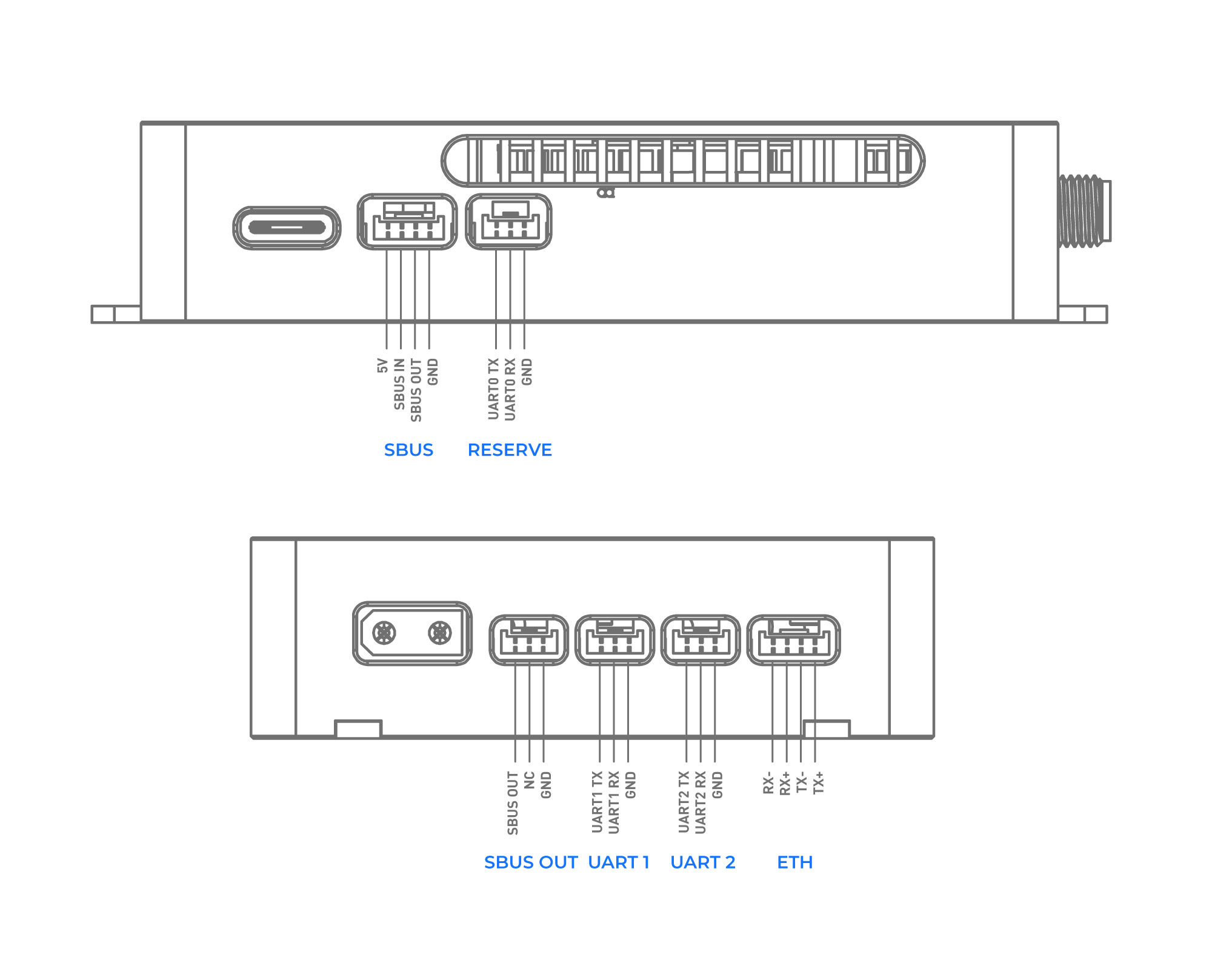
| Interface details | DC IN ×1, SBUS IN ×1, Serial Port ×2, Ethernet Port ×1 |
| Power consumption | Overall operating power consumption < 6 W |
| Heat dissipation | Built-in Active Cooling |
| Operating Temperature | -20°C ~ 75°C |
| Working voltage | 24±10V |
| Size | 91mm×61.2mm×18mm |
| Weight | 132g |
Interface Definition
Usage Notes
- The distance between the main antenna (MAIN ANT) and the secondary antenna (SLAVE ANT) should be greater than 20 cm. Antenna extension cables are included.
- The included omnidirectional antennas should be installed vertically upward on the ground side, and vertically upward or downward on the air side.
- The VSWR of the included omnidirectional antennas is lower when folded than when unfolded, resulting in better communication performance in the folded state.
- The antennas must not be placed directly against carbon fiber or metal, and there should be no metal or carbon fiber obstructions nearby.
- When the ground side and air side are within 2 meters of each other, the flight controller may fail to receive the relayed SBUS signal, and commands uploaded from the ground station may experience significant latency. Please increase the distance between the ground and air links.
Wiring method
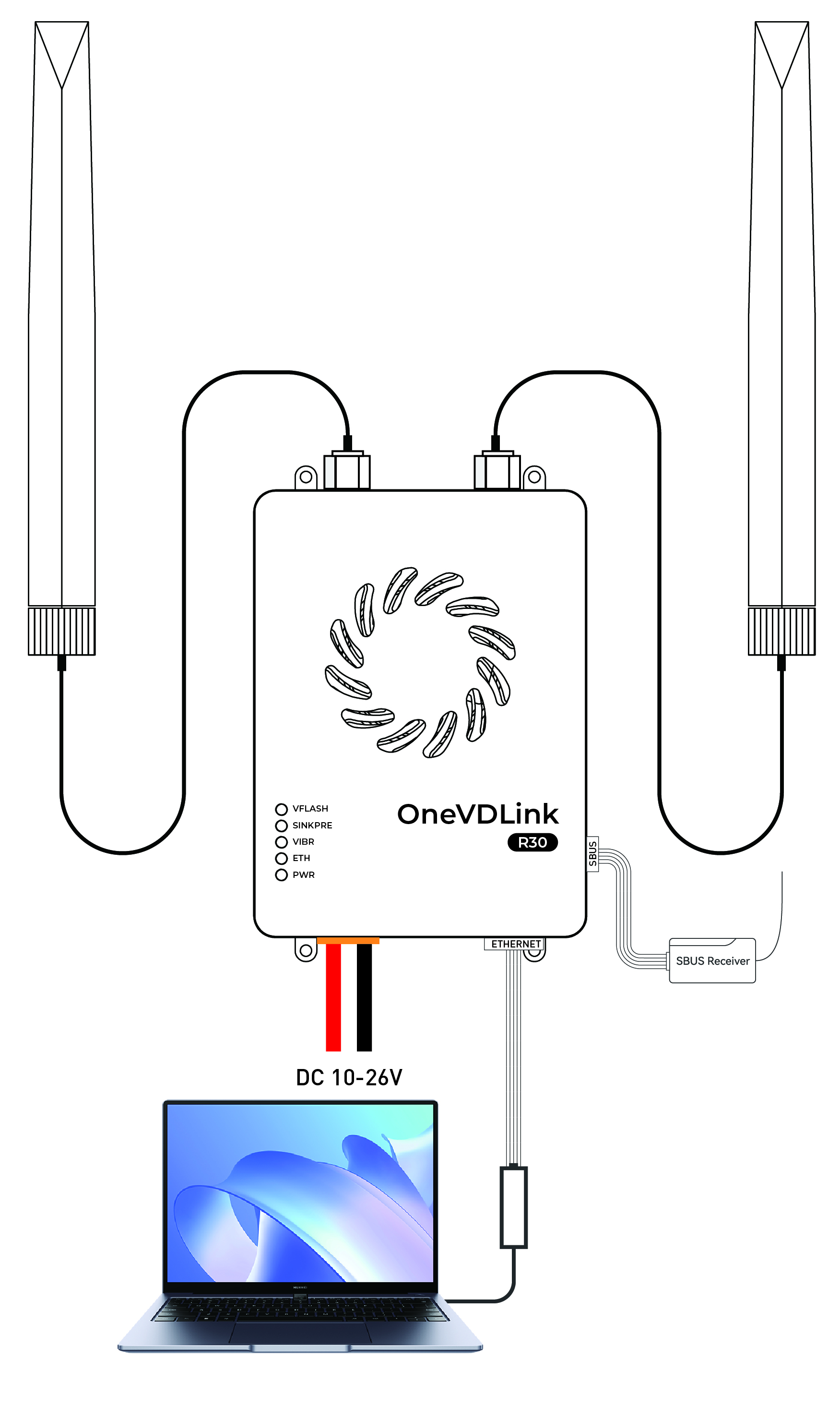
Ground Unit Connection Method
Connect the ground unit's Ethernet port to your laptop's Ethernet port. Power the ground unit with a 3–8S battery. The RC receiver can be connected to the SBUS interface of the OneVDLink.
The link supports receiver SBUS signal forwarding.
Air Unit Connection
There are two ways to connect the air unit to the flight controller for MAVLink data communication:
Connect the air unit's Ethernet port to the flight controller's Ethernet port.
Connect the air unit's UART to the flight controller's TELEM interface.
Using the UART connection is recommended, as this leaves the air unit's Ethernet port available for an Ethernet camera or gimbal.
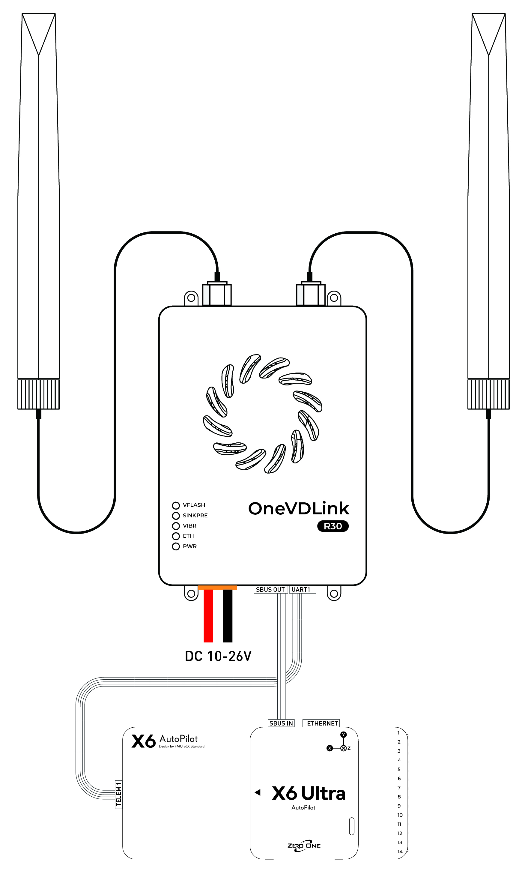
Using UART Communication
Connect UART1 of the air unit to TELEM1 of the flight controller, and set the flight controller parameter serial1_baud=115200 (a restart is required after modification).
Manually configure a static IP of 192.168.1.100 on the ground computer. In Mission Planner, select UDP port 14551 and click Connect. As shown below:
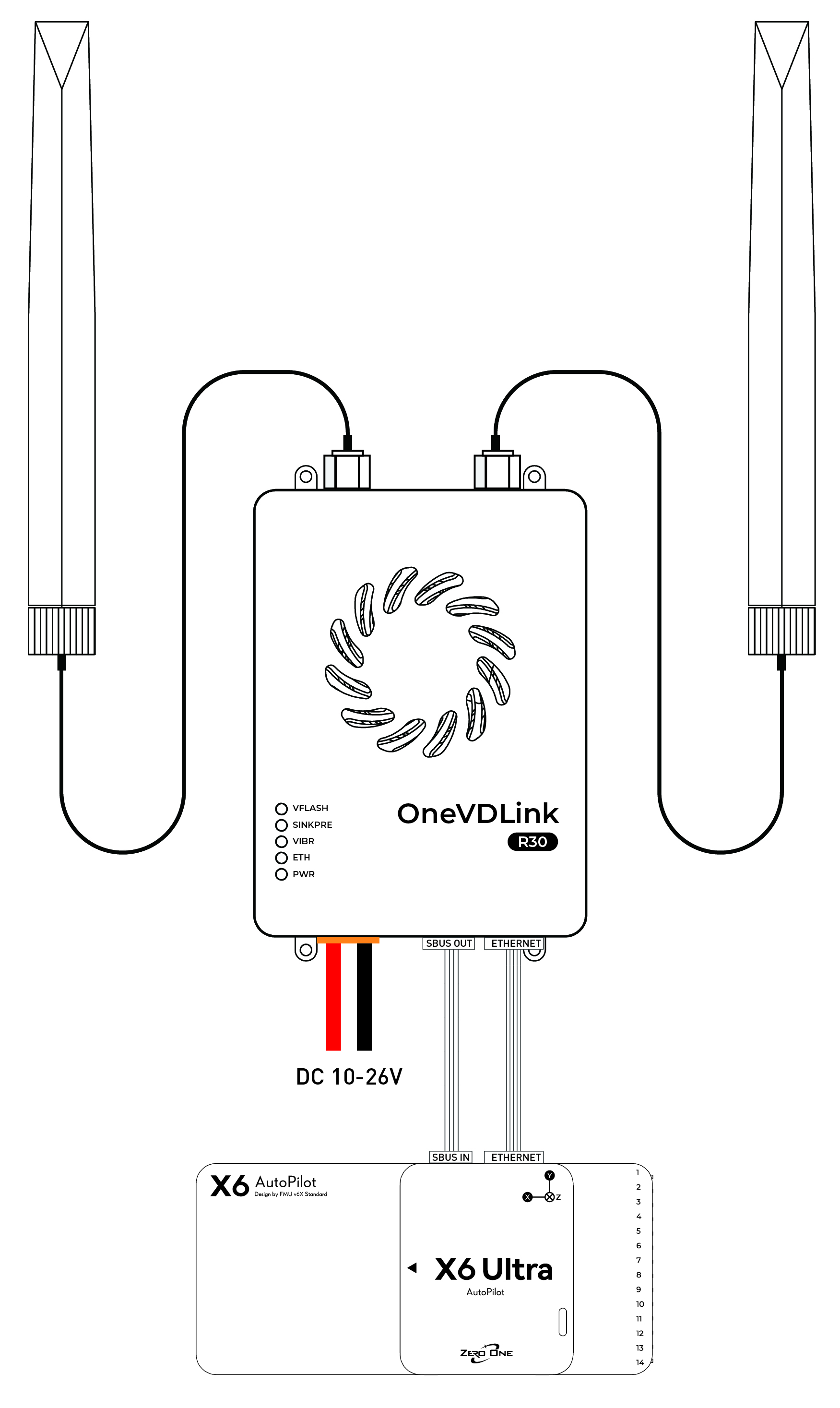
Using Ethernet Communication
Connect the air unit's Ethernet port to the flight controller's Ethernet port, and connect SBUS OUT to the flight controller's SBUS IN. Refer to the diagram below.
Configure the flight controller network parameters as follows:
net_enable=1
NET_DHCP=0
NET_P1_TYPE=1
NET_P1_PORT=15001 (configurable from 0 to 65535)
NET_P1_PROTOCOL=2
NET_P1_IP0=192
NET_P1_IP1=168
NET_P1_IP2=1
NET_P1_IP3=20 (The link device has already used 11 and 12 by default; do not configure the same IP)
On the ground computer, manually set a static IP address of 192.168.1.20. In Mission Planner, select UDP port 15001 and click Connect.
Default factory configuration: Point-to-point communication, ground unit IP 192.168.1.11, air unit IP 192.168.1.12, key 0001.
UART serial port interface configuration
Interface |
Configuration instructions |
Parameter Description |
|---|---|---|
| UART0 Switch It is recommended to keep it always on by default from the factory. |
At^uartipfun=1 |
1:Open |
| UART0 Basic Configuration Configure the baud rate, UDP port, and destination address. |
at^UARTIP="B115200",0,1,1,14550,"0.0.0.0",14550,"192.168.1.100" |
"B115200":Baud rate14550:Local/Remote UDP Port"0.0.0.0":Local IP (any)"192.168.1.100":Target IP address |
| UART0 MAVLink 2.0 Protocol Configuration Commonly used, recommended as the factory configuration, though not strictly required in actual testing. |
at^Uartipfrs=0at^uartipfrl=0at^Uartipfrs=1,1,fdat^uartipfrl=1,0,1,1,12 |
Used to configure the start condition, length, and parsing rules of serial data frames. |
| UART1/UART2 Switch It is recommended to keep it always on by default from the factory. |
At^uartfun=1 |
1:On (UART1 and UART2 share this switch) |
| UART1 Configuration Configure the network and serial port parameters for UART1. |
AT^UART1SET="192.168.1.100","14551","14551","B115200","8","1","N" |
"192.168.1.100":Target IP"14551":Local/remote ports"B115200":Baud rate"8":Data bit"1":Stop bit"N":No verification |
| UART2 Configuration Configure the network and serial port parameters for UART2. |
AT^UART2SET="192.168.1.100","14552","14552","B115200","8","1","N" |
"192.168.1.100":Target IP"14552":Local/remote ports"B115200":Baud rateOther parameters are the same as above |
Star Networking Tutorial
Central Node (Ground Unit)
| Central Node | Explanation |
|---|---|
AT+CFUN=0 |
Soft Shutdown |
AT^DAOCNDI=04 |
Set the frequency band to 1427.9–1447.9 MHz |
AT^DAPI="11223344" |
Set Access Key |
at^drps=14379,5,"26" |
Set the main antenna operating bandwidth to 20 MHz, transmit power to +26 dBm. |
AT^DFHC=1 |
Enable Automatic Frequency Hopping |
AT^ddtc=1 |
Set as Central Node |
AT^DSONSSF=9,0 |
Disable Wideband Adaptive |
AT^DSONSSF=7,0 |
Disable Point-to-Point Mode |
AT^DSTC=3 |
Set the uplink/downlink timeslot ratio to 4U1D |
at^netifcfg=2,"192.168.1.11" |
Set the network interface IP address to 192.168.1.11 |
AT^POWERCTL=1 |
Software Restart |
| Power Cycle | Physical Power Cycle |
Access Node (Air Unit)
| Configuration instructions | Explanation |
|---|---|
AT+CFUN=0 |
Soft Shutdown |
AT^DAOCNDI=04 |
Set the frequency band to 1427.9–1447.9 MHz |
AT^DAPI="11223344" |
Set Access Key |
AT^ddtc=2 |
Set as Access Node |
AT^DSONSSF=9,0 |
Disable Wideband Adaptive |
AT^DSONSSF=7,0 |
Disable Point-to-Point Mode |
AT^DSSMTP="26" |
Set the access node maximum transmit power to +26 dBm |
AT^DSTC=3 |
Set the uplink/downlink timeslot ratio to 4U1D |
at^netifcfg=2,"192.168.1.20" |
Set the IP address of Access Node 1 to 192.168.1.20, then restart after success. |
at^netifcfg=2,"192.168.1.21" |
Set the IP address of Access Node 2 to 192.168.1.21, then restart after success. |
at^netifcfg=2,"192.168.1.22" |
Set the IP address of Access Node 3 to 192.168.1.22, then restart after success. |
at^netifcfg=2,"192.168.1.23" |
Set the IP address of Access Node 4 to 192.168.1.23, then restart after success. |
at^netifcfg=2,"192.168.1.24" |
Set the IP address of Access Node 5 to 192.168.1.24, then restart after success. |
AT^POWERCTL=1 |
Software restart the device. |
| Power Cycle | Physical Power Cycle |
Frequently Asked Questions Troubleshooting Manual
1. Ethernet Port Issue: Unable to Connect to the R30 Web Interface
| Troubleshooting steps | Inspection items | Phenomenon/Instruction | Judgment and Solution |
|---|---|---|---|
| Step 1: LED Indicator | PWR (Power) LED: Red | Steady on | Steady on |
| Off | Module power supply is abnormal.Requires return to factory for repair. | ||
| ETH (Ethernet) Green LED | Steady on | 1. The Ethernet port chip is functioning normally. 2. Check the computer IP: Ensure it is on the same subnet as the R30 (e.g., 192.168.1.xx) and that the IP addresses do not conflict. |
|
| Off | 1. Check that the network cable is properly connected. 2. The Ethernet port chip is operating abnormally; further troubleshooting is required. |
||
| Step 2: AT Command Query | Check the actual IP configuration. | AT^NETIFCFG? |
Connect via USB and use the LCcom Tool to send the command to query the R30's current actual IP address, and verify it against the computer settings.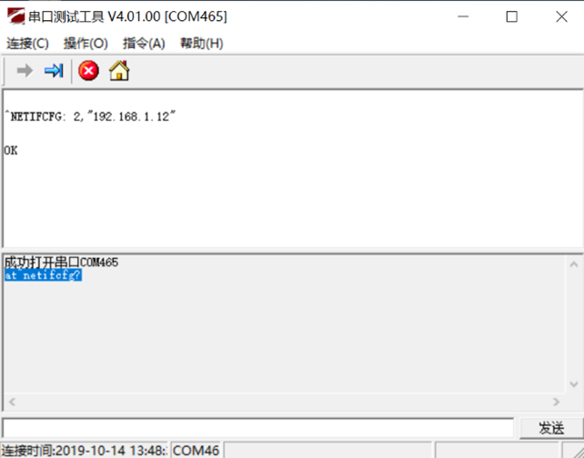 |
| Step 3: Initialization | Restore factory settings | AT^RECOVSET=1 |
When encountering other special situations, try initializing the module.Note: After initialization, the IP will revert to the default 192.168.1.12。 |
2. Link Issue: Web Interface Accessible but Unable to Establish Connection
| Troubleshooting steps | Inspection items | Phenomenon/Instruction | Judgment and Solution |
|---|---|---|---|
| Step 1: External Environment | Signal Interference | - | Check whether there is strong interference from nearby 1.4 GHz or 2.4 GHz signal sources. |
| Antenna Connection | - | Check that the antennas are correctly and securely connected to the device. | |
| Step 2: LED Indicator | Link Status LED | Central Node:VIBR blue LEDsteady on. Slave Node:VFLASH green LEDsteady on, VIBR blue LEDflashing. |
1. Verify that the device is correctly configured as a Central (Master) node or an Access (Slave) node. 2. Incorrect master/slave configuration will prevent link establishment. |
| Step 3: Web Configuration | Access Key | - | Ensure theAccess Keyis exactly the same on all devices. An incorrect key will prevent link establishment. |
| Operating Frequency Band | - | Ensure all devices are configured on thesame frequency band(e.g., 04 or 08). | |
| Step 4: AT Command Query | Continuous Transmission State | AT^DSONCTX? |
Query the current continuous transmission state; it must be OFF. |
;}.cls-2{fill:%230868f7;}.cls-3{fill:url(%23未命名的渐变_44);}.cls-4{fill:%23333;}%3c/style%3e%3clinearGradient%20id='未命名的渐变_8'%20x1='33.73'%20y1='100.61'%20x2='-0.03'%20y2='-1.06'%20gradientUnits='userSpaceOnUse'%3e%3cstop%20offset='0'%20stop-color='%237ae9fb'/%3e%3cstop%20offset='0.67'%20stop-color='%232b90f8'/%3e%3cstop%20offset='1'%20stop-color='%230868f7'/%3e%3c/linearGradient%3e%3clinearGradient%20id='未命名的渐变_44'%20x1='27.86'%20y1='18.67'%20x2='68.36'%20y2='22.22'%20gradientUnits='userSpaceOnUse'%3e%3cstop%20offset='0'%20stop-color='%235ac7f2'/%3e%3cstop%20offset='1'%20stop-color='%230868f7'/%3e%3c/linearGradient%3e%3c/defs%3e%3cpath%20class='cls-1'%20d='M29,28.74V81.91l-9.51-3.68v0L8.52,74A7.17,7.17,0,0,1,4,67.32V24.54A3.76,3.76,0,0,1,9.08,21Z'/%3e%3cpath%20class='cls-2'%20d='M68.09,78.07a13.15,13.15,0,0,1-17.9,12.06L29,81.91h0V28.74L50.19,37A13.17,13.17,0,0,0,68.08,25.3h0Z'/%3e%3cpath%20class='cls-3'%20d='M68.08,25.3a13.19,13.19,0,0,1-6.73,10.87A13.09,13.09,0,0,1,50.19,37L29,28.74V6A3.76,3.76,0,0,1,34.1,2.52l25.59,9.91A13.22,13.22,0,0,1,68.08,25.3Z'/%3e%3cpath%20class='cls-4'%20d='M129.06,81.76a4.33,4.33,0,0,1-3.19-1.31,4.4,4.4,0,0,1-1.31-3.24V56.86H97.65V77.21a4.36,4.36,0,0,1-1.35,3.2A4.68,4.68,0,0,1,93,81.76a4.32,4.32,0,0,1-3.19-1.31,4.37,4.37,0,0,1-1.32-3.24V27.27A4.58,4.58,0,0,1,89.83,24a4.59,4.59,0,0,1,7.82,3.27V48.15h26.91V27.27A4.58,4.58,0,0,1,125.91,24a4.59,4.59,0,0,1,7.82,3.27V77.21a4.37,4.37,0,0,1-1.36,3.2A4.65,4.65,0,0,1,129.06,81.76Z'/%3e%3cpath%20class='cls-4'%20d='M163.77,81.66c-6.57,0-11.76-1.92-15.44-5.7s-5.54-9.07-5.54-15.74a26.76,26.76,0,0,1,2.09-10.43,17.72,17.72,0,0,1,6.67-8.06,19.15,19.15,0,0,1,10.68-2.95,19,19,0,0,1,10.46,2.8,18.7,18.7,0,0,1,6.55,7.36,22.53,22.53,0,0,1,2.36,10.28A4.51,4.51,0,0,1,177,63.77H152.23a10.8,10.8,0,0,0,3.49,6.65c2,1.68,4.88,2.52,8.66,2.52a22.25,22.25,0,0,0,7.54-1.21c.74-.3,1.55-.67,2.37-1.07a3.75,3.75,0,0,1,1.84-.4,4.09,4.09,0,0,1,3,1.15,4,4,0,0,1,1.12,3,4.38,4.38,0,0,1-2.58,3.82,32.34,32.34,0,0,1-6.36,2.61A28.67,28.67,0,0,1,163.77,81.66ZM172.4,55.9a9.72,9.72,0,0,0-1.63-4.56A9.9,9.9,0,0,0,167,48a10.38,10.38,0,0,0-4.64-1.14,12,12,0,0,0-4.77,1.06,9.54,9.54,0,0,0-4.89,5.66,11.78,11.78,0,0,0-.51,2.3Z'/%3e%3cpath%20class='cls-4'%20d='M193,81.64a4.49,4.49,0,0,1-4.51-4.55V27.28A4.58,4.58,0,0,1,189.84,24a4.48,4.48,0,0,1,3.28-1.36A4.36,4.36,0,0,1,196.35,24a4.46,4.46,0,0,1,1.31,3.31V77.09a4.34,4.34,0,0,1-1.35,3.2A4.67,4.67,0,0,1,193,81.64Z'/%3e%3cpath%20class='cls-4'%20d='M263.79,81.71a5.7,5.7,0,0,1-4.2-1.74,5.76,5.76,0,0,1-1.73-4.19V27.37a4.58,4.58,0,0,1,1.35-3.27A4.59,4.59,0,0,1,267,27.37V72.53h24a4.58,4.58,0,0,1,3.27,7.82A4.66,4.66,0,0,1,291,81.71Z'/%3e%3cpath%20class='cls-4'%20d='M424.48,81.74a4.71,4.71,0,0,1-2.71-.88,5.43,5.43,0,0,1-1-1l-.07-.09-12.41-17-5.41,5v9.44a4.31,4.31,0,0,1-1.36,3.19,4.66,4.66,0,0,1-3.3,1.36A4.29,4.29,0,0,1,395,80.42a4.36,4.36,0,0,1-1.32-3.23V27.37A4.58,4.58,0,0,1,395,24.1a4.52,4.52,0,0,1,6.58.12,4.54,4.54,0,0,1,1.24,3.15V56.31l17.72-16.38.05,0a4.8,4.8,0,0,1,2.94-1.11,4.4,4.4,0,0,1,3.27,1.2,4.57,4.57,0,0,1,1.2,3.27,4.44,4.44,0,0,1-.77,2.33,7.45,7.45,0,0,1-1.43,1.65l-11,9.64,13.34,17.68a5,5,0,0,1,1,2.71,4.12,4.12,0,0,1-1.36,3.24A4.64,4.64,0,0,1,424.48,81.74Z'/%3e%3cpath%20class='cls-4'%20d='M317.93,81.76a21.5,21.5,0,1,1,21.17-21.5A21.37,21.37,0,0,1,317.93,81.76Zm0-34.1a12.61,12.61,0,1,0,12.42,12.6A12.52,12.52,0,0,0,317.93,47.66Z'/%3e%3cpath%20class='cls-4'%20d='M212.18,101.22a4.12,4.12,0,0,1-3.05-1.26,4.17,4.17,0,0,1-1.26-3.1V43.34a4.37,4.37,0,0,1,1.3-3.14,4.26,4.26,0,0,1,3.13-1.3,4.19,4.19,0,0,1,3.1,1.26,4.32,4.32,0,0,1,1.26,3.16,20.77,20.77,0,0,1,13-4.54,21.51,21.51,0,0,1,0,43,20.51,20.51,0,0,1-13-4.57V96.86a4.15,4.15,0,0,1-1.3,3.06A4.5,4.5,0,0,1,212.18,101.22Zm17.43-53.63c-6.23,0-12.93,4.11-12.93,12.72a12.73,12.73,0,0,0,25.46,0A12.71,12.71,0,0,0,229.61,47.59Z'/%3e%3cpath%20class='cls-4'%20d='M365.76,81.76a21.5,21.5,0,1,1,21.18-21.5A21.37,21.37,0,0,1,365.76,81.76Zm0-34.1a12.61,12.61,0,1,0,12.42,12.6A12.52,12.52,0,0,0,365.76,47.66Z'/%3e%3c/svg%3e)