X6 Air V2 Series Flight Controller Documentation
GCS Download
MissionPlanner GCS Download
https://firmware.ardupilot.org/Tools/MissionPlanner
QGC GCS Download
https://github.com/mavlink/qgroundcontrol/releases
Firmware Download
ArduPilot Firmware Download
PX4 Firmware Download
PX4 Firmware Flashing Precautions
During the firmware upgrade process using QGroundControl, please do not check [Advanced] and click [Flash ChibiOS Bootloader]. This operation will erase the flight controller's bootloader, causing certain interfaces (such as SBUS signal) to become unrecognizable and unable to function properly. The flight controller will need to be returned to the factory for repair, and the resulting after-sales shipping costs will be borne by the user. Please be aware.
For details, please refer to this flashing tutorial:PX4安装教程
Pinout Definition
PWM Output
- The X6_Air series flight controller supports up to 13 PWM outputs.
- The first 8 outputs (labeled 1 to 8) are controlled by a dedicated STM32F103 IO controller.
- The remaining 7 outputs (labeled 9 to 15) are "auxiliary" outputs. These are directly connected to the STM32H753 FMU controller.
- All 13 outputs support standard PWM output format. All 15 outputs support DShot except for output 15.
The 8 IO PWM outputs are divided into 4 groups:
- Outputs 1 and 2 are in Group 1.
- Outputs 3 and 4 are in Group 2.
- Outputs 5, 6, 7, and 8 are in Group 3.
The 7 FMU PWM outputs are divided into 4 groups:
- Outputs 1, 2, 3, and 4 are in Group 1.
- Outputs 5 and 6 are in Group 2.
- Output 7 is in Group 3.
- Outputs in the same group must use the same output rate. If any output in a group uses DShot, then all outputs in that group must use DShot.
GPIO Definition
All PWM outputs can be used as GPIOs (relays, cameras, tachometers, etc.). To use them, you need to set the output's SERVOx_FUNCTION to -1. In ArduPilot, the GPIO numbers used for PIN variables are as follows:
| IO Pin | FMU Pin | ||||
|---|---|---|---|---|---|
| Name | Value | Options | Name | Value | Options |
| M1 | 101 | MainOut1 | A9 | 50 | AuxOut1 |
| M2 | 102 | MainOut2 | A10 | 51 | AuxOut2 |
| M3 | 103 | MainOut3 | A11 | 52 | AuxOut3 |
| M4 | 104 | MainOut4 | A12 | 53 | AuxOut4 |
| M5 | 105 | MainOut5 | A13 | 54 | AuxOut5 |
| M6 | 106 | MainOut6 | A14 | 55 | AuxOut6 |
| M7 | 107 | MainOut7 | A15 | 56 | |
| M8 | 108 | MainOut8 |
Battery Monitoring
- The X6 Air series flight controller features a 6-pin power connector that supports CAN bus power supply.
- This is already configured by default in the firmware and typically requires no adjustment.
Analog Input
- The X6 Air series flight controller has 2 analog inputs.
- ADC Pin 12 -> ADC 6.6V Detection
- ADC Pin 13 -> ADC 3.3V Detection
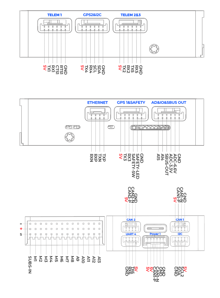
Interface Description
| Interface Name | Interface Description |
|---|---|
| Power 1 | Connect to OnePMU or other DroneCAN bus current sensors. |
| GPS1&Safety | Integrates Serial 3, safety switch, and LED — supports standard GPS modules. |
| GPS2 | GPS port, supports GPS or RTK connection, with integrated I2C bus pins. |
| TELEM1~3 | Connect to OneDLink, OneVDLink communication links or other MAVLink devices; can also connect to other serial communication devices. |
| CAN1~2 | Connect to DroneCAN/UAVCAN devices, such as OneGNSS, OneASP, OneRTK, etc. |
| SBUS IN | Connect to SBUS RC receiver. |
| SBUS OUT | SBUS signal output, used for gimbal control and other peripherals that support SBUS control. |
| I2C | Connect to I2C devices, such as I2C airspeed sensors. |
| M1-A15 | M1–A15: Supports PWM output, connectable to PWM ESCs or servos, camera shutter/hot shoe, etc. Of these, A14–A15 are extended via the supplied cable. A9–A15: Supports DShot protocol. |
| Type C | Connect to a computer for flight controller configuration, firmware flashing, etc. |
| TF Card Slot | Insert a memory card for log storage. Supports up to 256 GB, FAT32 format recommended. |
| ETHERNET | Ethernet port, for connecting Ethernet-enabled devices such as Ethernet gimbals, Raspberry Pi, NVIDIA Jetson series boards, etc. |
| AD&IO&SBUS OUT | Integrated ADC for analog current sensor, SBUS OUT, and IO pins A14–A15. |
Serial Port Mapping
In the pinout diagram above, the UARTs are labeled as Rn and Tn. The Rn pin is the receive pin for UARTn. The Tn pin is the transmit pin for UARTn.
| Name | Function | MCU PINS | DMA |
|---|---|---|---|
| SERIAL0 | OTG1 | USB | |
| SERIAL1 | Telem1 | UART7 | DMA Enabled |
| SERIAL2 | Telem2 | UART5 | DMA Enabled |
| SERIAL3 | GPS1 | USART1 | DMA Enabled |
| SERIAL4 | GPS2 | UART8 | DMA Enabled |
| SERIAL5 | Telem3 | USART2 | DMA Enabled |
| SERIAL6 | UART4 | UART4 | DMA Enabled |
| SERIAL7 | OTG-SLCAN | USB |
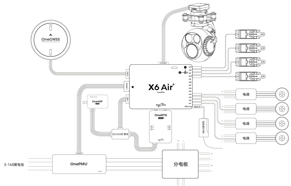
Hardware Connection
The following wiring diagram illustrates the wiring method for a typical VTOL (Vertical Take-Off and Landing) drone. The connections are for reference only; users should add devices and adjust the interface configuration according to their own aircraft model and requirements. For the function of each interface, please refer to the Interface Definition.
4-in-1 ESC Wiring Reference:
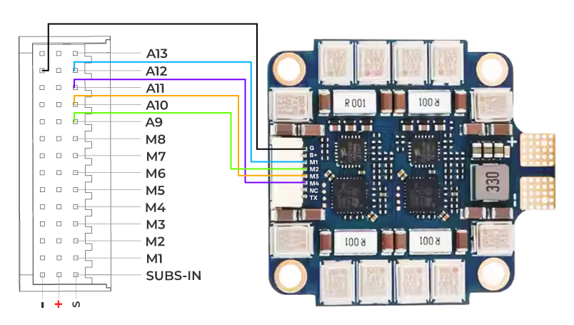
Note
The above wiring is for reference only. Please be sure to check that the motor numbering is correct. If not, adjust the signal wire connection sequence accordingly. Typically, 4-in-1 ESCs are designed for FPV racing drones running Betaflight firmware, and the motor numbering differs from that used by ArduPilot firmware.
X6 Air+ V2 Flight Controller Specifications
| Item | X6 Air | X6 Air+ |
|---|---|---|
| MCU | STM32H743 | STM32H743 |
| IO MCU | STM32F103 | STM32F103 |
| Accelerometer & Gyroscope | IIM42652 | IIM42652+ICM45686 |
| Compass | BMM350 | BMM350 |
| Barometer | BMP581 | BMP581+SPL07 |
| Receiver Protocol Input | SBUS | SBUS |
| PWM Output | PWM Output: 15 (13 Dupont connectors, 2 GH 1.25 connectors) | PWM Output: 15 (13 Dupont connectors, 2 GH 1.25 connectors) |
| Power Interface | 1 | 1 |
| Servo Voltage Monitoring | 9.9V | 9.9V |
| Built-in Vibration Damping | No | Yes |
| IMU Temperature Compensation System | No | Yes |
| Interface Details | CAN×2 Telem ×3 GPS&Safety ×1 GPS2×1 ETH ×1 UART 4×1 SBUS IN×1 SBUS OUT×1 AD&IO ×1 I2C ×1 | CAN×2 Telem ×3 GPS&Safety ×1 GPS2×1 ETH ×1 UART 4×1 SBUS IN×1 SBUS OUT×1 AD&IO ×1 I2C ×1 |
| Operating Temperature | -20℃ ~ 85℃ | -20℃ ~ 85℃ |
| Weight | 36g | 38g |
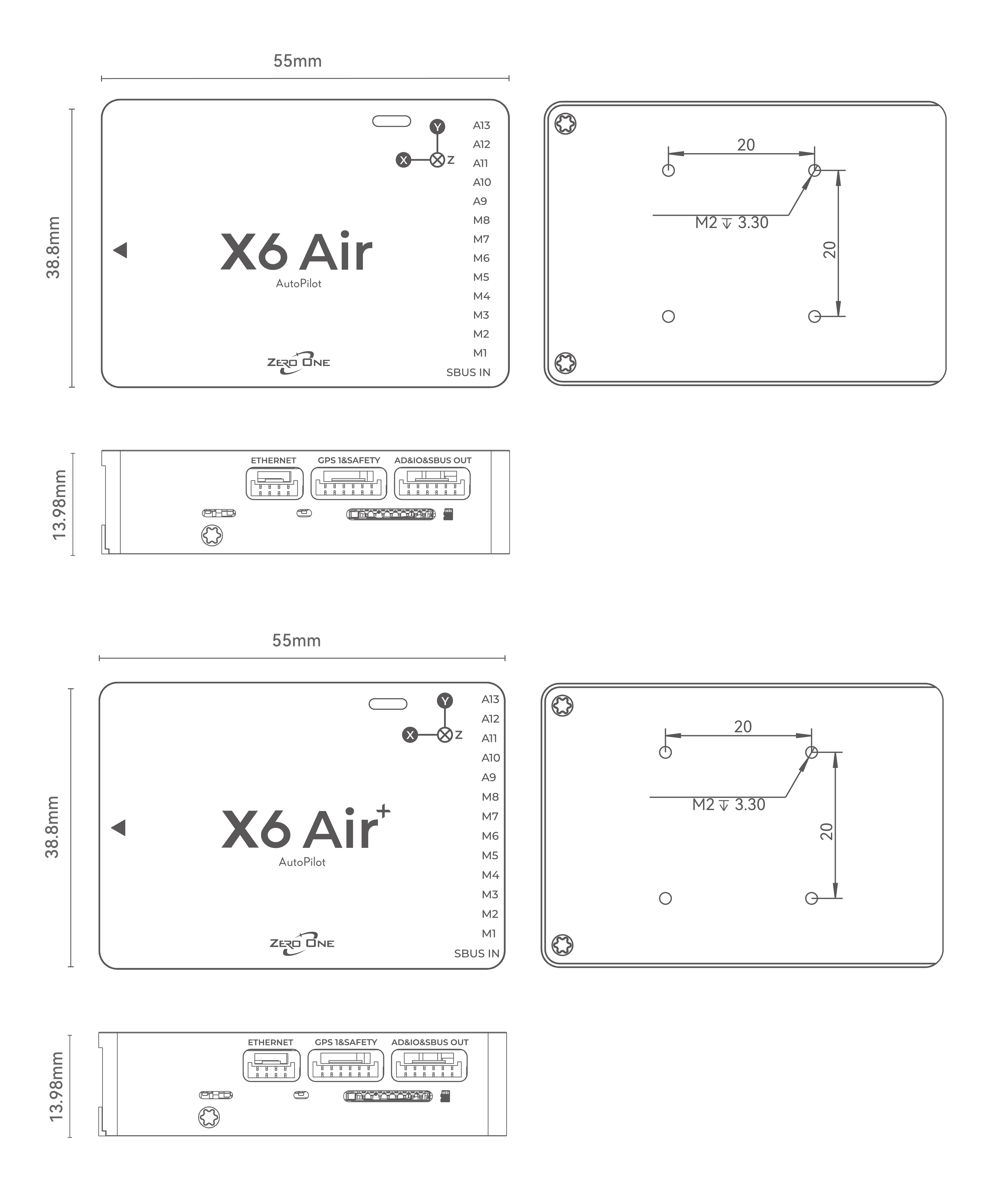
| Size | 55mm×38.8mm×14mm | 55mm×38.8mm×14mm |
| Firmware Support | ArduPilot 4.5.6 or later, PX4 1.16.1 beta or later | ArduPilot 4.5.6 or later; PX4 1.16.1 beta or later |
| Supported Vehicle Types | Helicopters, multicopters, Plane, VTOL , UGVs, USVs, etc. | Helicopters, multicopters, Plane, VTOL , UGVs, USVs, etc. |
| Operating Voltage | 4.5V-5.4V | 4.5V-5.4V |
X6 Air+ Dimensions and Mounting Hole Diagram
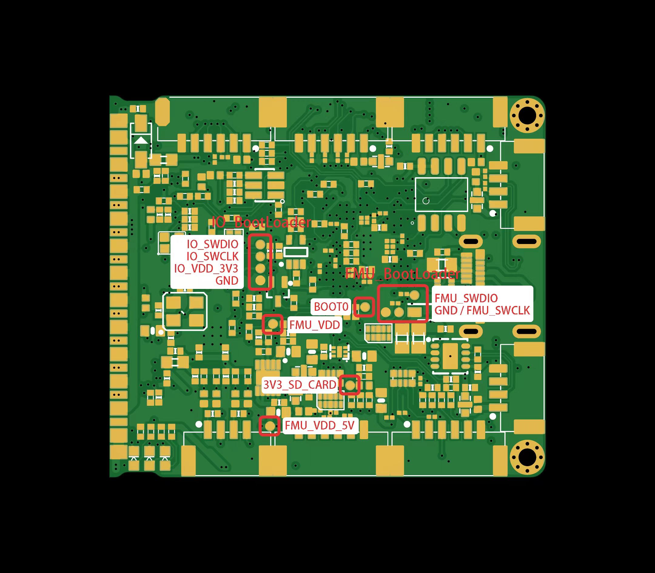
Debug Interface
Safety Notice
1.This product is not intended for use by persons under 18 years of age. Individuals under 18 should only use it under adult supervision.
2.This product is an open-source flight controller. Users must possess professional knowledge of open-source drones and be capable of correctly configuring and operating the drone.
3.Do not fly in strong wind conditions.
4.The flight controller itself is not waterproof. Do not fly in the rain.
5.Please abide by local laws and regulations. Without proper local permission, do not fly in crowded areas, train stations, airports, or other sensitive areas to avoid endangering public safety.
6.Before takeoff, carefully check that all connections are secure, all devices are functioning properly, and all control responses are correct to prevent accidents.
7.Perform routine maintenance before and after each flight. Check for loose hardware connections, damaged motor blades/propellers, and the tightness of screws.
8.High-speed rotating propellers are extremely dangerous. Keep a safe distance from people while flying. Never operate or fly under the influence of alcohol, fatigue, or any other impaired mental state.
;}.cls-2{fill:%230868f7;}.cls-3{fill:url(%23未命名的渐变_44);}.cls-4{fill:%23333;}%3c/style%3e%3clinearGradient%20id='未命名的渐变_8'%20x1='33.73'%20y1='100.61'%20x2='-0.03'%20y2='-1.06'%20gradientUnits='userSpaceOnUse'%3e%3cstop%20offset='0'%20stop-color='%237ae9fb'/%3e%3cstop%20offset='0.67'%20stop-color='%232b90f8'/%3e%3cstop%20offset='1'%20stop-color='%230868f7'/%3e%3c/linearGradient%3e%3clinearGradient%20id='未命名的渐变_44'%20x1='27.86'%20y1='18.67'%20x2='68.36'%20y2='22.22'%20gradientUnits='userSpaceOnUse'%3e%3cstop%20offset='0'%20stop-color='%235ac7f2'/%3e%3cstop%20offset='1'%20stop-color='%230868f7'/%3e%3c/linearGradient%3e%3c/defs%3e%3cpath%20class='cls-1'%20d='M29,28.74V81.91l-9.51-3.68v0L8.52,74A7.17,7.17,0,0,1,4,67.32V24.54A3.76,3.76,0,0,1,9.08,21Z'/%3e%3cpath%20class='cls-2'%20d='M68.09,78.07a13.15,13.15,0,0,1-17.9,12.06L29,81.91h0V28.74L50.19,37A13.17,13.17,0,0,0,68.08,25.3h0Z'/%3e%3cpath%20class='cls-3'%20d='M68.08,25.3a13.19,13.19,0,0,1-6.73,10.87A13.09,13.09,0,0,1,50.19,37L29,28.74V6A3.76,3.76,0,0,1,34.1,2.52l25.59,9.91A13.22,13.22,0,0,1,68.08,25.3Z'/%3e%3cpath%20class='cls-4'%20d='M129.06,81.76a4.33,4.33,0,0,1-3.19-1.31,4.4,4.4,0,0,1-1.31-3.24V56.86H97.65V77.21a4.36,4.36,0,0,1-1.35,3.2A4.68,4.68,0,0,1,93,81.76a4.32,4.32,0,0,1-3.19-1.31,4.37,4.37,0,0,1-1.32-3.24V27.27A4.58,4.58,0,0,1,89.83,24a4.59,4.59,0,0,1,7.82,3.27V48.15h26.91V27.27A4.58,4.58,0,0,1,125.91,24a4.59,4.59,0,0,1,7.82,3.27V77.21a4.37,4.37,0,0,1-1.36,3.2A4.65,4.65,0,0,1,129.06,81.76Z'/%3e%3cpath%20class='cls-4'%20d='M163.77,81.66c-6.57,0-11.76-1.92-15.44-5.7s-5.54-9.07-5.54-15.74a26.76,26.76,0,0,1,2.09-10.43,17.72,17.72,0,0,1,6.67-8.06,19.15,19.15,0,0,1,10.68-2.95,19,19,0,0,1,10.46,2.8,18.7,18.7,0,0,1,6.55,7.36,22.53,22.53,0,0,1,2.36,10.28A4.51,4.51,0,0,1,177,63.77H152.23a10.8,10.8,0,0,0,3.49,6.65c2,1.68,4.88,2.52,8.66,2.52a22.25,22.25,0,0,0,7.54-1.21c.74-.3,1.55-.67,2.37-1.07a3.75,3.75,0,0,1,1.84-.4,4.09,4.09,0,0,1,3,1.15,4,4,0,0,1,1.12,3,4.38,4.38,0,0,1-2.58,3.82,32.34,32.34,0,0,1-6.36,2.61A28.67,28.67,0,0,1,163.77,81.66ZM172.4,55.9a9.72,9.72,0,0,0-1.63-4.56A9.9,9.9,0,0,0,167,48a10.38,10.38,0,0,0-4.64-1.14,12,12,0,0,0-4.77,1.06,9.54,9.54,0,0,0-4.89,5.66,11.78,11.78,0,0,0-.51,2.3Z'/%3e%3cpath%20class='cls-4'%20d='M193,81.64a4.49,4.49,0,0,1-4.51-4.55V27.28A4.58,4.58,0,0,1,189.84,24a4.48,4.48,0,0,1,3.28-1.36A4.36,4.36,0,0,1,196.35,24a4.46,4.46,0,0,1,1.31,3.31V77.09a4.34,4.34,0,0,1-1.35,3.2A4.67,4.67,0,0,1,193,81.64Z'/%3e%3cpath%20class='cls-4'%20d='M263.79,81.71a5.7,5.7,0,0,1-4.2-1.74,5.76,5.76,0,0,1-1.73-4.19V27.37a4.58,4.58,0,0,1,1.35-3.27A4.59,4.59,0,0,1,267,27.37V72.53h24a4.58,4.58,0,0,1,3.27,7.82A4.66,4.66,0,0,1,291,81.71Z'/%3e%3cpath%20class='cls-4'%20d='M424.48,81.74a4.71,4.71,0,0,1-2.71-.88,5.43,5.43,0,0,1-1-1l-.07-.09-12.41-17-5.41,5v9.44a4.31,4.31,0,0,1-1.36,3.19,4.66,4.66,0,0,1-3.3,1.36A4.29,4.29,0,0,1,395,80.42a4.36,4.36,0,0,1-1.32-3.23V27.37A4.58,4.58,0,0,1,395,24.1a4.52,4.52,0,0,1,6.58.12,4.54,4.54,0,0,1,1.24,3.15V56.31l17.72-16.38.05,0a4.8,4.8,0,0,1,2.94-1.11,4.4,4.4,0,0,1,3.27,1.2,4.57,4.57,0,0,1,1.2,3.27,4.44,4.44,0,0,1-.77,2.33,7.45,7.45,0,0,1-1.43,1.65l-11,9.64,13.34,17.68a5,5,0,0,1,1,2.71,4.12,4.12,0,0,1-1.36,3.24A4.64,4.64,0,0,1,424.48,81.74Z'/%3e%3cpath%20class='cls-4'%20d='M317.93,81.76a21.5,21.5,0,1,1,21.17-21.5A21.37,21.37,0,0,1,317.93,81.76Zm0-34.1a12.61,12.61,0,1,0,12.42,12.6A12.52,12.52,0,0,0,317.93,47.66Z'/%3e%3cpath%20class='cls-4'%20d='M212.18,101.22a4.12,4.12,0,0,1-3.05-1.26,4.17,4.17,0,0,1-1.26-3.1V43.34a4.37,4.37,0,0,1,1.3-3.14,4.26,4.26,0,0,1,3.13-1.3,4.19,4.19,0,0,1,3.1,1.26,4.32,4.32,0,0,1,1.26,3.16,20.77,20.77,0,0,1,13-4.54,21.51,21.51,0,0,1,0,43,20.51,20.51,0,0,1-13-4.57V96.86a4.15,4.15,0,0,1-1.3,3.06A4.5,4.5,0,0,1,212.18,101.22Zm17.43-53.63c-6.23,0-12.93,4.11-12.93,12.72a12.73,12.73,0,0,0,25.46,0A12.71,12.71,0,0,0,229.61,47.59Z'/%3e%3cpath%20class='cls-4'%20d='M365.76,81.76a21.5,21.5,0,1,1,21.18-21.5A21.37,21.37,0,0,1,365.76,81.76Zm0-34.1a12.61,12.61,0,1,0,12.42,12.6A12.52,12.52,0,0,0,365.76,47.66Z'/%3e%3c/svg%3e)