X6 Ultra AutoPilot Instruction
Ground Station Download
MissionPlanner Ground Station Download
https://firmware.ardupilot.org/Tools/MissionPlanner
QGC Ground Station Download:
https://github.com/mavlink/qgroundcontrol/releases
Firmware Download
ArduPilot Firmware Download
| Firmware Version | HeliCopter | MultiRotor | Plane | Rover | Sub | Blimp |
|---|---|---|---|---|---|---|
| 4.7.0 | Download | Download | Download | Download |
PX4 Firmware Download
| Firmware Version | X6 Ultra |
|---|---|
| 1.16 | Download Link |
PX4 Flashing Precautions
When using the QGC Ground Station to upgrade the firmware, please DO NOT check 【Advanced】 and click 【Flash ChibiOS Bootloader】. This operation will erase the flight controller's Bootloader, causing issues such as inability to recognize SBUS signals and some interfaces malfunctioning. This will require factory repair, and the resulting after-sales shipping costs will be borne by the user. Please be advised!
For specific instructions, please refer to this flashing tutorial: PX4 Installation Tutorial
Interface Definition
Interface Description
| Interface Name | Interface Description |
|---|---|
| Power 1~ 2 | Connect OnePMU or other DroneCAN bus current meters |
| GPS&Safety | Can connect PX4 standard type GPS, integrated with safety switch, compass, buzzer, and LED light |
| GPS 2 | GPS interface, can connect GPS or RTK, integrated with I2C bus pins |
| TELEM1~3 | Connect OneDLink, OneVDLink telemetry radios or other MavLink devices, also can connect other serial communication devices. TELEM 1 is SERIAL1, TELEM2 is SERIAL2, TELEM3 is SERIAL5 |
| CAN1~2 | Connect DroneCAN/UAVCAN devices, such as OneGNSS, OneASP, OneRTK, etc. GPS1 is SERIAL3, GPS2 is SERIAL4 |
| SBUS IN | Connect SBUS remote control receiver |
| SBUS OUT | SBUS signal output, used for gimbal control and other peripherals that support SBUS control |
| DSM PPM IN | This interface integrates DSM and PPM remote control receivers, and RSSI signal strength input. |
| M1-M16 | M1-M16: Support PWM output, can connect PWM ESCs or servos, connect camera shutter/hot shoe, etc. M15-M16 are expanded via the provided cable. M1-M14 support Dshot protocol; M9-M14 support Bidirectional Dshot |
| Type C | Connect to computer for flight controller configuration, firmware flashing, etc. |
| USB | GH1.25 USB expansion interface |
| I2C | Connect I2C devices, such as I2C airspeed sensor |
| TF Card Slot | Install memory card for storing logs, supports up to 256G, FAT32 format recommended |
| ETHERNET | Ethernet interface, connect devices supporting network communication, such as Ethernet gimbals, Raspberry Pi, NVIDIA Jetson series boards, etc. |
| AD&IO | Integrated BootLoader interface, analog-to-digital converter, can connect analog current meter |
| SPI | Connect external SPI sensors |
| IO Debug | Connecting this interface requires opening the bottom cover. For professionals and developers. |
| FMU Debug | Connecting this interface requires opening the bottom cover. For professionals and developers. |
PWM Level Switching
The flight controller outputs 3.3V level voltage by default. When your device's signal cable is too long (exceeding 75cm), it is recommended to change it to 5.0V level voltage. However, please ensure your peripheral supports this voltage (please consult your hardware equipment manufacturer for confirmation). The modification method is as follows:
After connecting to Mission Planner, search for the parameter BRD_PWM_VOLT_SEL in the full parameter list. The default is 0, representing 3.3V level. Change it to 1, write the parameters, and restart the flight controller/re-power it to take effect.
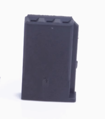
PWM Connector Recommendation
The PWM terminals on the X6 Ultra flight controller have a custom 2.6mm pitch. It is recommended that users use Futaba 3-pin Dupont male right-angle connectors, as shown in the figure below:
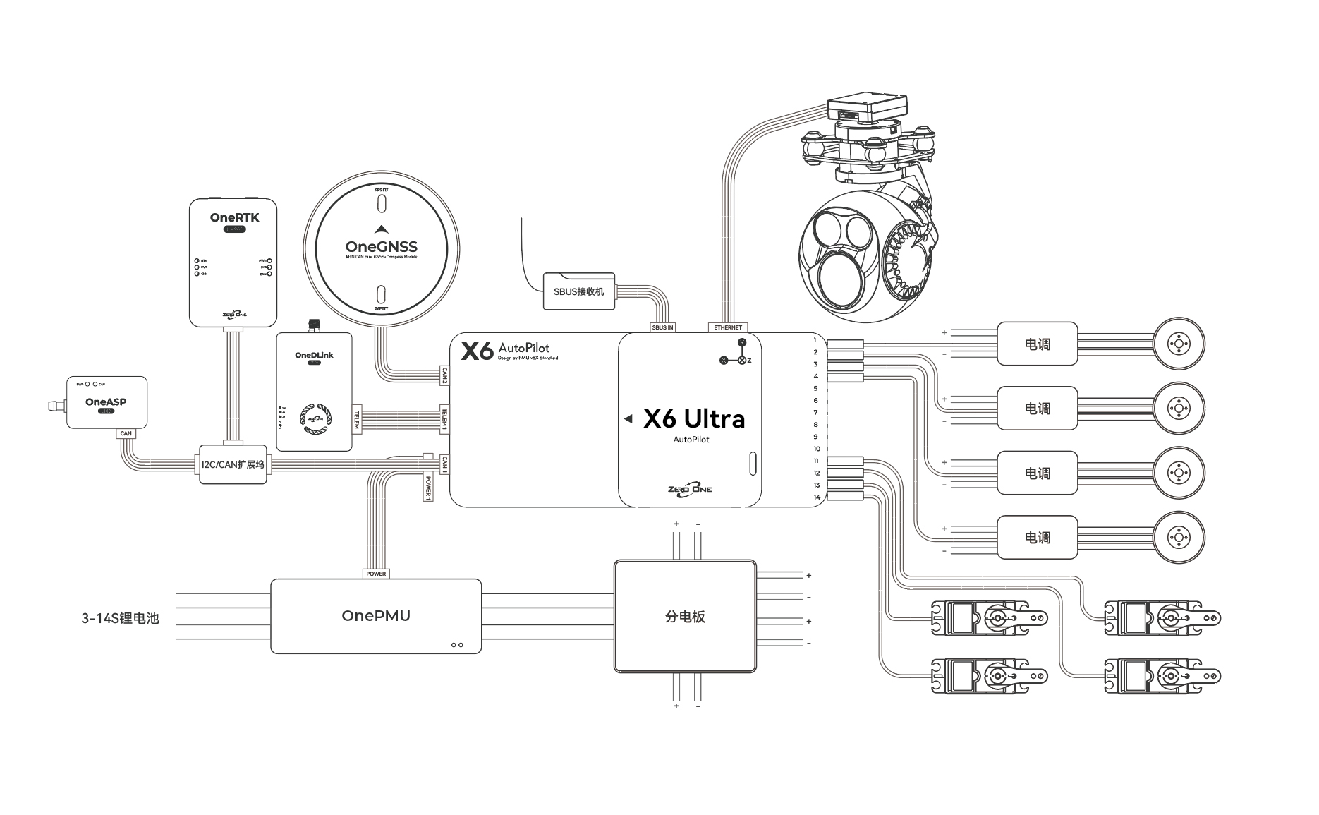
Wiring Instructions
The following wiring diagram introduces the wiring method for a conventional Vertical Take-Off and Landing (VTOL) drone. The connection method is for reference only. Users need to add devices and adjust the interface methods according to their own aircraft model and requirements. Please refer to the previous interface description for the function of each interface.
X6 Ultra Flight Controller Specifications Table
| Item | Specification |
|---|---|
| Hardware Standard | FMU v6X |
| MCU | STM32H753 |
| IO MCU | STM32F103 |
| Built-in Shock Absorption | Yes |
| Accelerometer and Gyroscope | SCH16T (Tactical-grade) + IIM42653/IIM42652 (Industrial-grade) x2 |
| Barometer | ICP-20100×2 |
| Magnetometer (Compass) | RM3100 |
| PWM Relay | Yes |
| Remote Control Protocol Input | SBUS + DSM + PPM |
| PWM Channels | 16 (14 Dupont interfaces + 2 GH1.25 expansion interfaces) |
| PWM Level Switching | Supports switching between 3.3V and 5V |
| Power Interface | 2x DroneCAN Power Interfaces |
| Servo Voltage Monitoring | 9.9V |
| Interface Details | CAN×2, GPS&Safety×1, GPS2×1, DSM PPM IN×1, ETH×1, UART 4×1, SBUS IN×1, USB×1, SPI×1, AD&IO×1, I2C×1 |
| Operating Temperature | -20℃~85℃ |
| Weight | 97g |
| Aircraft Type Support | Helicopter, Multirotor, Fixed-wing, VTOL Fixed-wing, Unmanned Car, Unmanned Boat |
| Operating Voltage | 4.5V-5.4V |
X6 Ultra Flight Controller Dimensions and Mounting Hole Diagram

Safety Instructions
- This product is not intended for use by persons under the age of 18. Persons under 18 years of age should use it under the supervision of an adult.
- This product is an open-source flight controller. Users must possess professional knowledge of open-source drones and be able to correctly configure and operate the drone.
- Do not fly in strong wind conditions.
- The flight controller itself is not waterproof. Do not fly in rain.
- Please comply with local laws and regulations. Do not fly in crowded areas, train stations, airports, or other sensitive areas without obtaining local permission, to avoid endangering public safety.
- Before takeoff, a thorough inspection must be carried out to ensure all connections are secure, all equipment is functioning properly, and all control actions respond correctly, to prevent accidents.
- Routine maintenance should be performed before and after each flight, checking for loose hardware connections, damage to motors and propellers, screw tightness, etc.
- High-speed rotating propellers are extremely dangerous. Please pay attention to safety during flight and keep away from crowds. Do not operate or fly under the influence of alcohol, when fatigued, or in any other impaired mental state.
;}.cls-2{fill:%230868f7;}.cls-3{fill:url(%23未命名的渐变_44);}.cls-4{fill:%23333;}%3c/style%3e%3clinearGradient%20id='未命名的渐变_8'%20x1='33.73'%20y1='100.61'%20x2='-0.03'%20y2='-1.06'%20gradientUnits='userSpaceOnUse'%3e%3cstop%20offset='0'%20stop-color='%237ae9fb'/%3e%3cstop%20offset='0.67'%20stop-color='%232b90f8'/%3e%3cstop%20offset='1'%20stop-color='%230868f7'/%3e%3c/linearGradient%3e%3clinearGradient%20id='未命名的渐变_44'%20x1='27.86'%20y1='18.67'%20x2='68.36'%20y2='22.22'%20gradientUnits='userSpaceOnUse'%3e%3cstop%20offset='0'%20stop-color='%235ac7f2'/%3e%3cstop%20offset='1'%20stop-color='%230868f7'/%3e%3c/linearGradient%3e%3c/defs%3e%3cpath%20class='cls-1'%20d='M29,28.74V81.91l-9.51-3.68v0L8.52,74A7.17,7.17,0,0,1,4,67.32V24.54A3.76,3.76,0,0,1,9.08,21Z'/%3e%3cpath%20class='cls-2'%20d='M68.09,78.07a13.15,13.15,0,0,1-17.9,12.06L29,81.91h0V28.74L50.19,37A13.17,13.17,0,0,0,68.08,25.3h0Z'/%3e%3cpath%20class='cls-3'%20d='M68.08,25.3a13.19,13.19,0,0,1-6.73,10.87A13.09,13.09,0,0,1,50.19,37L29,28.74V6A3.76,3.76,0,0,1,34.1,2.52l25.59,9.91A13.22,13.22,0,0,1,68.08,25.3Z'/%3e%3cpath%20class='cls-4'%20d='M129.06,81.76a4.33,4.33,0,0,1-3.19-1.31,4.4,4.4,0,0,1-1.31-3.24V56.86H97.65V77.21a4.36,4.36,0,0,1-1.35,3.2A4.68,4.68,0,0,1,93,81.76a4.32,4.32,0,0,1-3.19-1.31,4.37,4.37,0,0,1-1.32-3.24V27.27A4.58,4.58,0,0,1,89.83,24a4.59,4.59,0,0,1,7.82,3.27V48.15h26.91V27.27A4.58,4.58,0,0,1,125.91,24a4.59,4.59,0,0,1,7.82,3.27V77.21a4.37,4.37,0,0,1-1.36,3.2A4.65,4.65,0,0,1,129.06,81.76Z'/%3e%3cpath%20class='cls-4'%20d='M163.77,81.66c-6.57,0-11.76-1.92-15.44-5.7s-5.54-9.07-5.54-15.74a26.76,26.76,0,0,1,2.09-10.43,17.72,17.72,0,0,1,6.67-8.06,19.15,19.15,0,0,1,10.68-2.95,19,19,0,0,1,10.46,2.8,18.7,18.7,0,0,1,6.55,7.36,22.53,22.53,0,0,1,2.36,10.28A4.51,4.51,0,0,1,177,63.77H152.23a10.8,10.8,0,0,0,3.49,6.65c2,1.68,4.88,2.52,8.66,2.52a22.25,22.25,0,0,0,7.54-1.21c.74-.3,1.55-.67,2.37-1.07a3.75,3.75,0,0,1,1.84-.4,4.09,4.09,0,0,1,3,1.15,4,4,0,0,1,1.12,3,4.38,4.38,0,0,1-2.58,3.82,32.34,32.34,0,0,1-6.36,2.61A28.67,28.67,0,0,1,163.77,81.66ZM172.4,55.9a9.72,9.72,0,0,0-1.63-4.56A9.9,9.9,0,0,0,167,48a10.38,10.38,0,0,0-4.64-1.14,12,12,0,0,0-4.77,1.06,9.54,9.54,0,0,0-4.89,5.66,11.78,11.78,0,0,0-.51,2.3Z'/%3e%3cpath%20class='cls-4'%20d='M193,81.64a4.49,4.49,0,0,1-4.51-4.55V27.28A4.58,4.58,0,0,1,189.84,24a4.48,4.48,0,0,1,3.28-1.36A4.36,4.36,0,0,1,196.35,24a4.46,4.46,0,0,1,1.31,3.31V77.09a4.34,4.34,0,0,1-1.35,3.2A4.67,4.67,0,0,1,193,81.64Z'/%3e%3cpath%20class='cls-4'%20d='M263.79,81.71a5.7,5.7,0,0,1-4.2-1.74,5.76,5.76,0,0,1-1.73-4.19V27.37a4.58,4.58,0,0,1,1.35-3.27A4.59,4.59,0,0,1,267,27.37V72.53h24a4.58,4.58,0,0,1,3.27,7.82A4.66,4.66,0,0,1,291,81.71Z'/%3e%3cpath%20class='cls-4'%20d='M424.48,81.74a4.71,4.71,0,0,1-2.71-.88,5.43,5.43,0,0,1-1-1l-.07-.09-12.41-17-5.41,5v9.44a4.31,4.31,0,0,1-1.36,3.19,4.66,4.66,0,0,1-3.3,1.36A4.29,4.29,0,0,1,395,80.42a4.36,4.36,0,0,1-1.32-3.23V27.37A4.58,4.58,0,0,1,395,24.1a4.52,4.52,0,0,1,6.58.12,4.54,4.54,0,0,1,1.24,3.15V56.31l17.72-16.38.05,0a4.8,4.8,0,0,1,2.94-1.11,4.4,4.4,0,0,1,3.27,1.2,4.57,4.57,0,0,1,1.2,3.27,4.44,4.44,0,0,1-.77,2.33,7.45,7.45,0,0,1-1.43,1.65l-11,9.64,13.34,17.68a5,5,0,0,1,1,2.71,4.12,4.12,0,0,1-1.36,3.24A4.64,4.64,0,0,1,424.48,81.74Z'/%3e%3cpath%20class='cls-4'%20d='M317.93,81.76a21.5,21.5,0,1,1,21.17-21.5A21.37,21.37,0,0,1,317.93,81.76Zm0-34.1a12.61,12.61,0,1,0,12.42,12.6A12.52,12.52,0,0,0,317.93,47.66Z'/%3e%3cpath%20class='cls-4'%20d='M212.18,101.22a4.12,4.12,0,0,1-3.05-1.26,4.17,4.17,0,0,1-1.26-3.1V43.34a4.37,4.37,0,0,1,1.3-3.14,4.26,4.26,0,0,1,3.13-1.3,4.19,4.19,0,0,1,3.1,1.26,4.32,4.32,0,0,1,1.26,3.16,20.77,20.77,0,0,1,13-4.54,21.51,21.51,0,0,1,0,43,20.51,20.51,0,0,1-13-4.57V96.86a4.15,4.15,0,0,1-1.3,3.06A4.5,4.5,0,0,1,212.18,101.22Zm17.43-53.63c-6.23,0-12.93,4.11-12.93,12.72a12.73,12.73,0,0,0,25.46,0A12.71,12.71,0,0,0,229.61,47.59Z'/%3e%3cpath%20class='cls-4'%20d='M365.76,81.76a21.5,21.5,0,1,1,21.18-21.5A21.37,21.37,0,0,1,365.76,81.76Zm0-34.1a12.61,12.61,0,1,0,12.42,12.6A12.52,12.52,0,0,0,365.76,47.66Z'/%3e%3c/svg%3e)