WebUI User Manual
Computer network configuration
Setup steps
- The PC needs to be configured with an IP address on the same subnet as the terminal device. For example, if the terminal device IP address is 192.168.1.11, configure the PC as follows:
- Ethernet Properties → Internet Protocol Version 4 (TCP/IPv4) Properties
- Select "Use the following IP address"
- IP address: 192.168.1.150
- Subnet mask: 255.255.255.0
- Default gateway: (leave blank)
- DNS server address: (configure as needed or leave blank)
Note: The PC must be configured on the same subnet as the terminal device to ensure normal access to the WebUI interface, and its IP address must not conflict with the master or slave device IPs.
WebUI Instructions
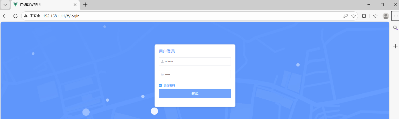
User login
- Default username and password: admin / admin
- Default IPs in the initial version: ground unit 192.168.1.11, air unit 192.168.1.12
- Default login URL: http://192.168.1.12/#/login
Network status
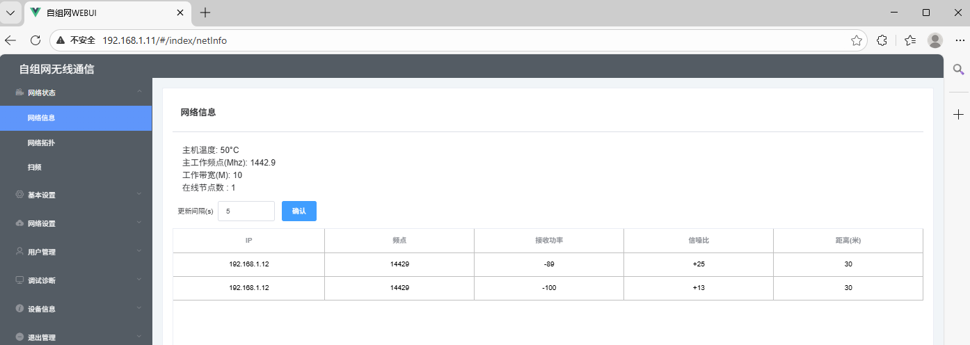
1.1 Network Information
-
Displays the core networking information of the device, including CPU temperature, operating frequency, operating bandwidth, number of online nodes, number of neighboring nodes, and the automatic link information update interval.
-
-
Link Information Details: Detected neighbor node's IP, EARFCN (operating frequency), RSRP (Reference Signal Received Power), SNR (Signal-to-Noise Ratio), DISTANCE (distance to the critical point).
-
Update Interval: Configurable time interval for updating link information with neighboring nodes.
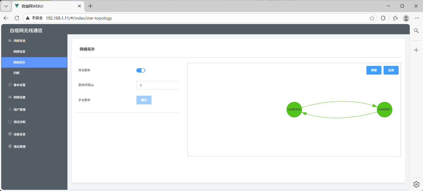
1.2 Network Topology
-
After successful networking, the Network Topology page displays the current network topology. It auto-refreshes by default and supports manually setting the refresh interval.
-
In automatic update mode, you can click the Pop-up or Full-screen button to display the topology interface in a pop-up window or in full-screen mode.
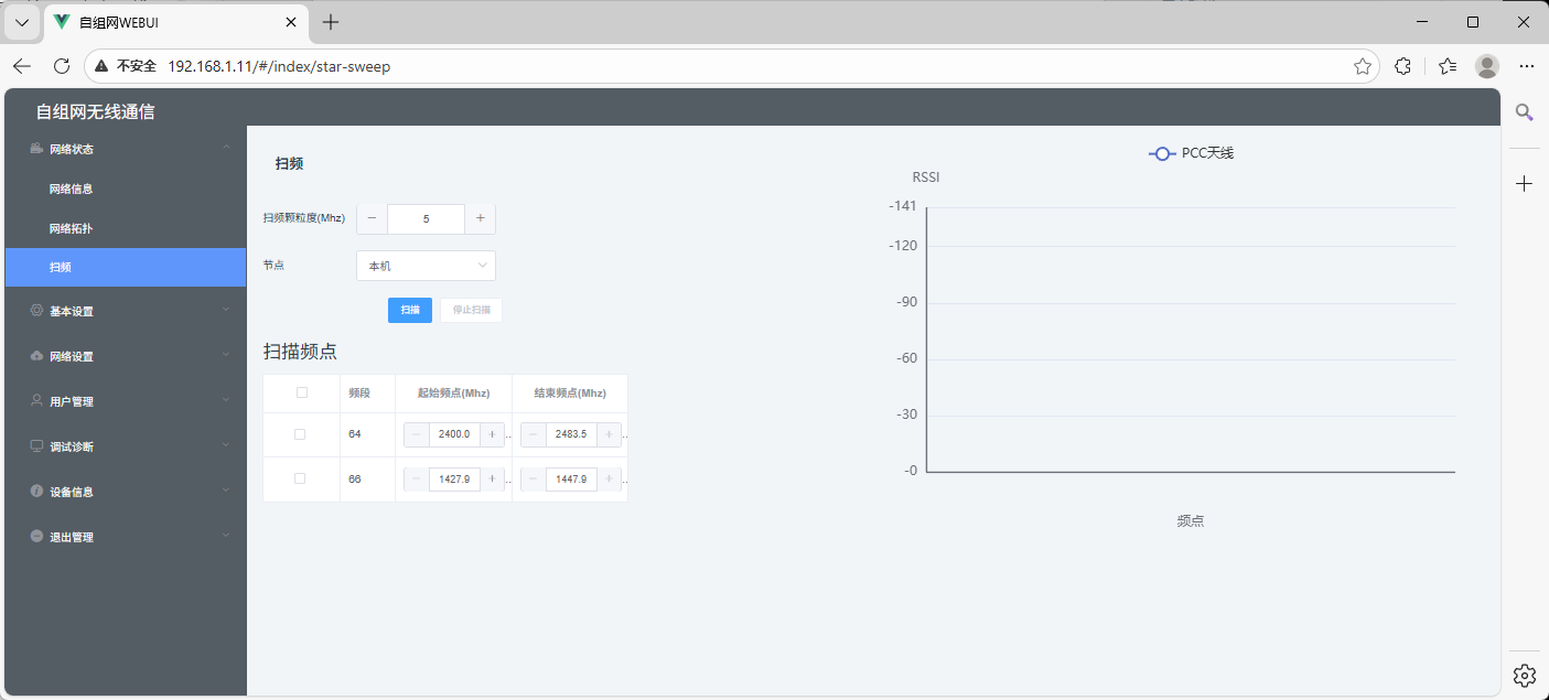
1.3 Frequency Scan
-
Function: Scan the surrounding radio environment for interference.
-
Operation: Supports scanning by selecting different frequency points. The more frequency points selected, the longer the scanning time.
-
Interference Judgment Criteria: Compare the sampled value with the threshold set in the AT command. If it exceeds the threshold, interference is considered present; otherwise, no interference is detected.
Basic Settings
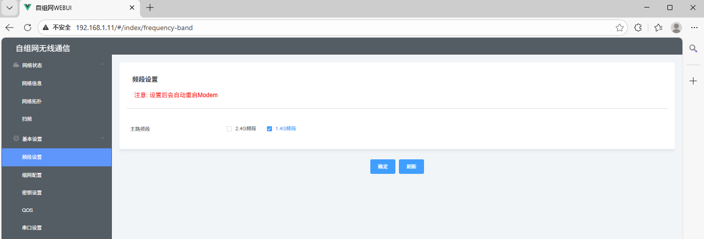
Frequency band setting
- Default supported frequency points are all selected by default. Click the checkbox to deselect or select the frequency band to configure.
- Operation: Click "OK" to save and apply the settings.
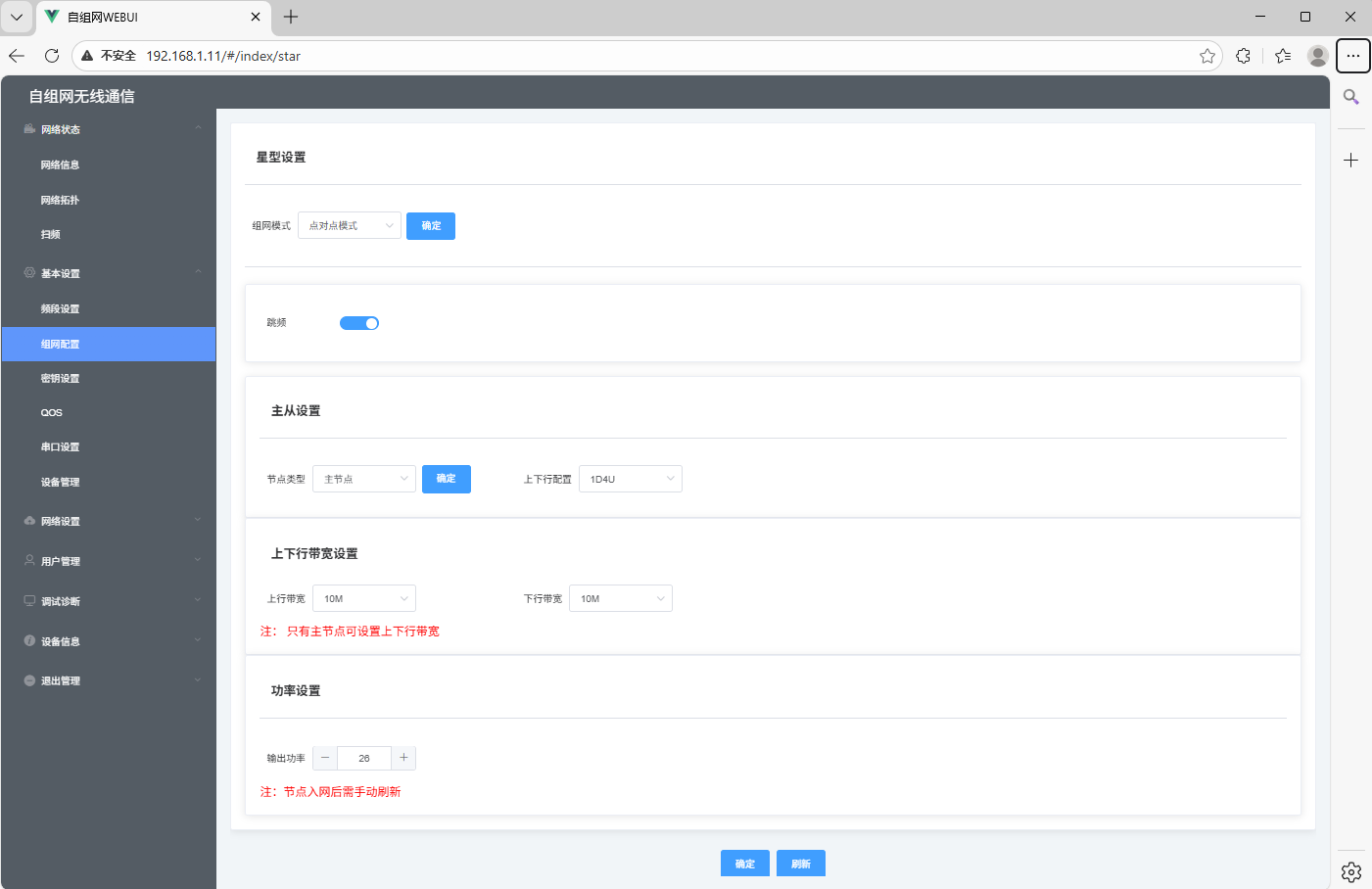
Networking Settings
- This interface allows configuration of the node's operating mode, frequency hopping, bandwidth, power, and frequency points. Detailed configuration instructions are as follows:
- Work Mode: The device defaults to point-to-point mode and can be configured for two operating modes, including star networking.
- Frequency Hopping: Enable or disable the frequency hopping function. Click the blue area next to the button to change the configuration; the change is automatically saved and takes effect immediately.
- Node Settings: Allows configuration of the master node, slave node, and uplink/downlink settings.
- Bandwidth: Default bandwidth is 20 MHz. Five options are available: 20M, 10M, 5M, 3M, and 1.4M. After configuration, click OK at the bottom of the interface to save and apply the settings.
- Output Power: Default transmit power is 26 dBm, adjustable according to actual conditions. After configuration, click OK at the bottom of the interface to save and apply the settings.
- Frequency Point Setting: Grayed out by default. The frequency hopping function must be disabled before configuring the primary and secondary frequency points of the device.
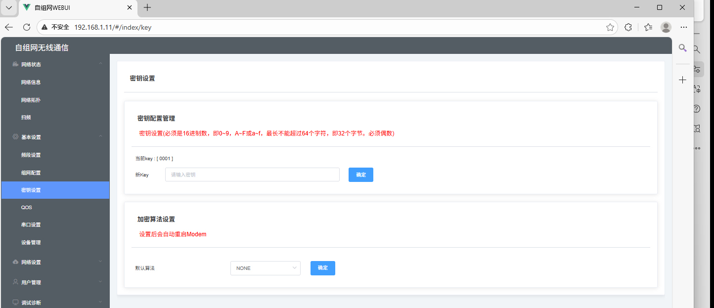
Key setting
- Function: Key configuration management and encryption algorithm settings
- Key configuration requirements:
- All devices must have exactly the same key, otherwise they cannot form a network.
- The key must be a hexadecimal number (0–9, A–F or a–f).
- It must not exceed 64 characters (i.e., 32 bytes).
- The key must have an even number of characters.
- Encryption algorithm: Default is SNOW3G. Four options are provided: "NONE", "SNOW3G", "AES", "ZUC". When forming a network, the encryption algorithm must be configured identically on all devices.
Equipment Management
- Function: Restart the device or restore factory settings.
- Restart Device: Click the "Restart Device" button, and the device will restart automatically. Some parameter changes require a restart to take effect, which can be performed using this button.
- Restore Factory Settings: Click the "Restore Factory Settings" button, and all device configurations will be restored to factory defaults.

Network Settings
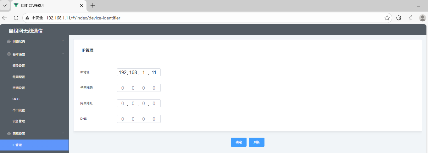
IP Management
- Function: Configure the device's IP address, subnet mask, gateway, and DNS according to actual conditions.
- The configuration interface provides input fields for the corresponding parameters. After filling them in, save to apply the settings.
User Management
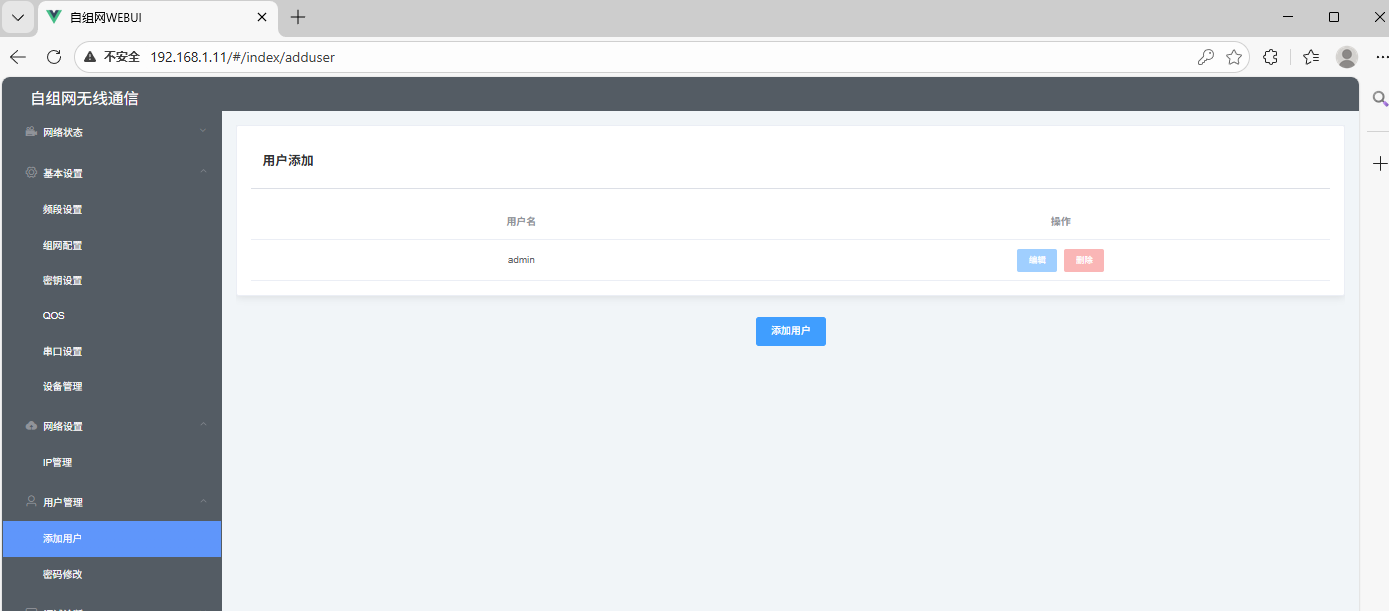
Add user
- Function: Add administrator users or manage existing administrator accounts.
- Steps:
- Click the "Add User" button to open the Add User interface.
- Enter a username and a password of at least 6 characters.
- Click "OK" to complete adding the administrator.
- The interface includes an "Add User" button and a list of added users (displaying user status and other information).
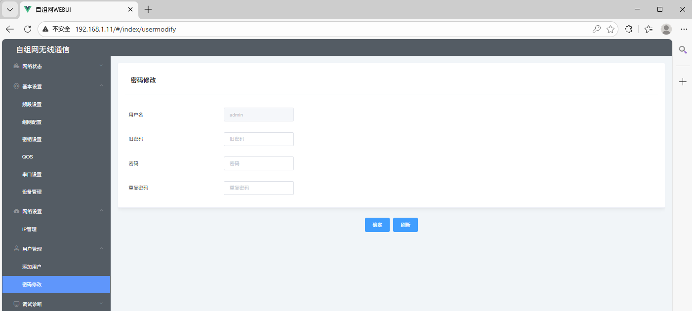
Change password
- Function: Change the administrator account password (default administrator username and password: admin/admin).
- Interface: Contains Old Password, New Password, and Confirm New Password input fields. Fill them in and submit to apply the change.
Debugging and diagnostics
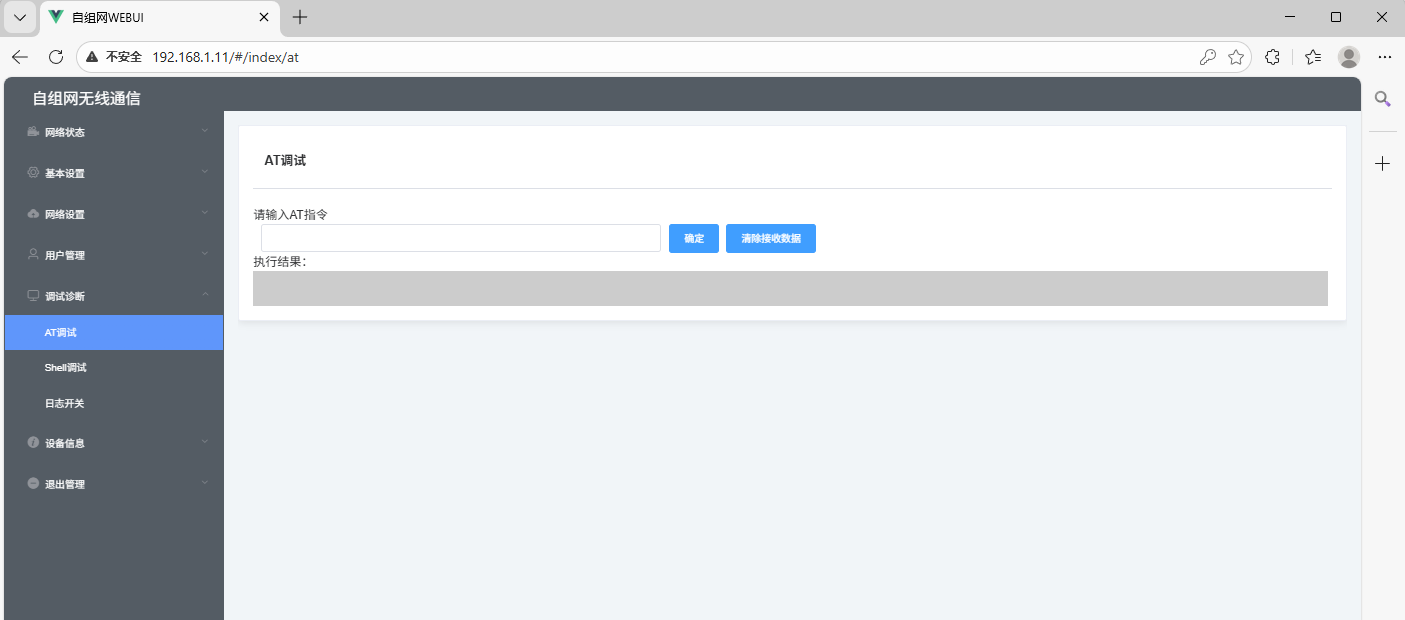
AT Debugging
- Function: Configure, restart, reset, etc. the device by entering AT commands.
- Operation: Enter an AT command in the input box and click OK to send the command; the Clear received data button clears the display of execution results.
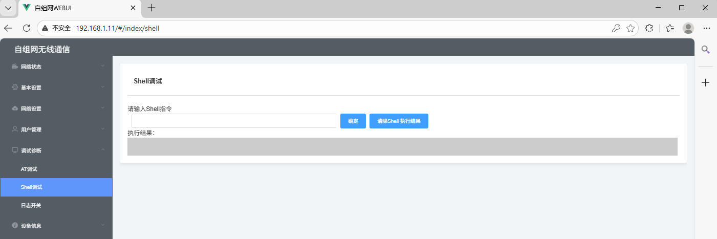
Shell debugging
- Function: Manage the device by executing certain shell commands.
- Interface: Includes a command input area and an execution result display area (showing device running status information, such as uptime, etc).
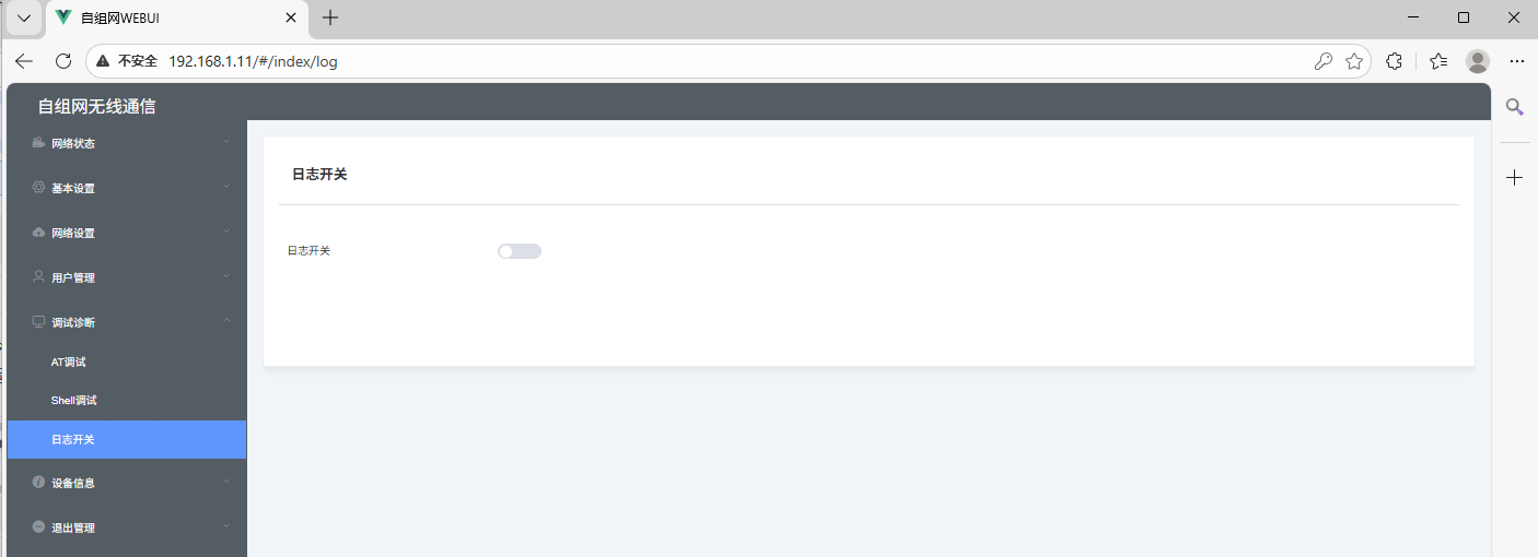
Log switch
- Function: Enable or disable the device LOG function. When LOG is enabled, the device automatically generates system LOGs in the background.
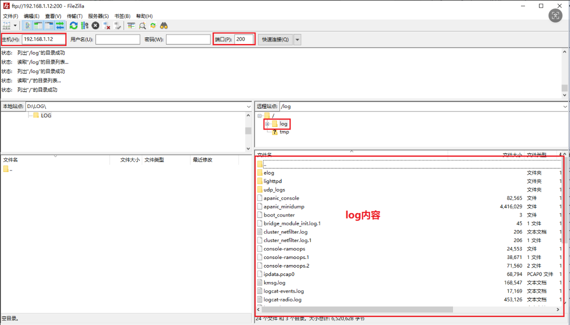
- Export LOG method:
- After generating logs, use an FTP client to connect to port 200 of the device.
- Drag the LOG folder from the "Remote site" to the "Local site" to export the device logs.
- Device logs can also be deleted via this FTP connection.
Version Information
- The interface displays the device's current full system version information and modem version information (e.g., C77K-11002, CV.10.02R262023102_WFFL, SONV3.10.02R26_20231012_WFHS, etc.).
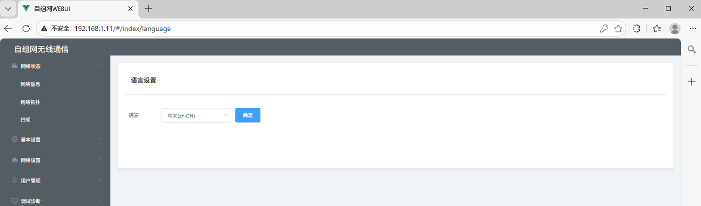
Language settings
Switchable between Chinese and English
Exit Management
- Operation: Click the "Exit" button on this interface to display the logout confirmation dialog.
- After confirming, you will be logged out of the device management interface and returned to the login page.
;}.cls-2{fill:%230868f7;}.cls-3{fill:url(%23未命名的渐变_44);}.cls-4{fill:%23333;}%3c/style%3e%3clinearGradient%20id='未命名的渐变_8'%20x1='33.73'%20y1='100.61'%20x2='-0.03'%20y2='-1.06'%20gradientUnits='userSpaceOnUse'%3e%3cstop%20offset='0'%20stop-color='%237ae9fb'/%3e%3cstop%20offset='0.67'%20stop-color='%232b90f8'/%3e%3cstop%20offset='1'%20stop-color='%230868f7'/%3e%3c/linearGradient%3e%3clinearGradient%20id='未命名的渐变_44'%20x1='27.86'%20y1='18.67'%20x2='68.36'%20y2='22.22'%20gradientUnits='userSpaceOnUse'%3e%3cstop%20offset='0'%20stop-color='%235ac7f2'/%3e%3cstop%20offset='1'%20stop-color='%230868f7'/%3e%3c/linearGradient%3e%3c/defs%3e%3cpath%20class='cls-1'%20d='M29,28.74V81.91l-9.51-3.68v0L8.52,74A7.17,7.17,0,0,1,4,67.32V24.54A3.76,3.76,0,0,1,9.08,21Z'/%3e%3cpath%20class='cls-2'%20d='M68.09,78.07a13.15,13.15,0,0,1-17.9,12.06L29,81.91h0V28.74L50.19,37A13.17,13.17,0,0,0,68.08,25.3h0Z'/%3e%3cpath%20class='cls-3'%20d='M68.08,25.3a13.19,13.19,0,0,1-6.73,10.87A13.09,13.09,0,0,1,50.19,37L29,28.74V6A3.76,3.76,0,0,1,34.1,2.52l25.59,9.91A13.22,13.22,0,0,1,68.08,25.3Z'/%3e%3cpath%20class='cls-4'%20d='M129.06,81.76a4.33,4.33,0,0,1-3.19-1.31,4.4,4.4,0,0,1-1.31-3.24V56.86H97.65V77.21a4.36,4.36,0,0,1-1.35,3.2A4.68,4.68,0,0,1,93,81.76a4.32,4.32,0,0,1-3.19-1.31,4.37,4.37,0,0,1-1.32-3.24V27.27A4.58,4.58,0,0,1,89.83,24a4.59,4.59,0,0,1,7.82,3.27V48.15h26.91V27.27A4.58,4.58,0,0,1,125.91,24a4.59,4.59,0,0,1,7.82,3.27V77.21a4.37,4.37,0,0,1-1.36,3.2A4.65,4.65,0,0,1,129.06,81.76Z'/%3e%3cpath%20class='cls-4'%20d='M163.77,81.66c-6.57,0-11.76-1.92-15.44-5.7s-5.54-9.07-5.54-15.74a26.76,26.76,0,0,1,2.09-10.43,17.72,17.72,0,0,1,6.67-8.06,19.15,19.15,0,0,1,10.68-2.95,19,19,0,0,1,10.46,2.8,18.7,18.7,0,0,1,6.55,7.36,22.53,22.53,0,0,1,2.36,10.28A4.51,4.51,0,0,1,177,63.77H152.23a10.8,10.8,0,0,0,3.49,6.65c2,1.68,4.88,2.52,8.66,2.52a22.25,22.25,0,0,0,7.54-1.21c.74-.3,1.55-.67,2.37-1.07a3.75,3.75,0,0,1,1.84-.4,4.09,4.09,0,0,1,3,1.15,4,4,0,0,1,1.12,3,4.38,4.38,0,0,1-2.58,3.82,32.34,32.34,0,0,1-6.36,2.61A28.67,28.67,0,0,1,163.77,81.66ZM172.4,55.9a9.72,9.72,0,0,0-1.63-4.56A9.9,9.9,0,0,0,167,48a10.38,10.38,0,0,0-4.64-1.14,12,12,0,0,0-4.77,1.06,9.54,9.54,0,0,0-4.89,5.66,11.78,11.78,0,0,0-.51,2.3Z'/%3e%3cpath%20class='cls-4'%20d='M193,81.64a4.49,4.49,0,0,1-4.51-4.55V27.28A4.58,4.58,0,0,1,189.84,24a4.48,4.48,0,0,1,3.28-1.36A4.36,4.36,0,0,1,196.35,24a4.46,4.46,0,0,1,1.31,3.31V77.09a4.34,4.34,0,0,1-1.35,3.2A4.67,4.67,0,0,1,193,81.64Z'/%3e%3cpath%20class='cls-4'%20d='M263.79,81.71a5.7,5.7,0,0,1-4.2-1.74,5.76,5.76,0,0,1-1.73-4.19V27.37a4.58,4.58,0,0,1,1.35-3.27A4.59,4.59,0,0,1,267,27.37V72.53h24a4.58,4.58,0,0,1,3.27,7.82A4.66,4.66,0,0,1,291,81.71Z'/%3e%3cpath%20class='cls-4'%20d='M424.48,81.74a4.71,4.71,0,0,1-2.71-.88,5.43,5.43,0,0,1-1-1l-.07-.09-12.41-17-5.41,5v9.44a4.31,4.31,0,0,1-1.36,3.19,4.66,4.66,0,0,1-3.3,1.36A4.29,4.29,0,0,1,395,80.42a4.36,4.36,0,0,1-1.32-3.23V27.37A4.58,4.58,0,0,1,395,24.1a4.52,4.52,0,0,1,6.58.12,4.54,4.54,0,0,1,1.24,3.15V56.31l17.72-16.38.05,0a4.8,4.8,0,0,1,2.94-1.11,4.4,4.4,0,0,1,3.27,1.2,4.57,4.57,0,0,1,1.2,3.27,4.44,4.44,0,0,1-.77,2.33,7.45,7.45,0,0,1-1.43,1.65l-11,9.64,13.34,17.68a5,5,0,0,1,1,2.71,4.12,4.12,0,0,1-1.36,3.24A4.64,4.64,0,0,1,424.48,81.74Z'/%3e%3cpath%20class='cls-4'%20d='M317.93,81.76a21.5,21.5,0,1,1,21.17-21.5A21.37,21.37,0,0,1,317.93,81.76Zm0-34.1a12.61,12.61,0,1,0,12.42,12.6A12.52,12.52,0,0,0,317.93,47.66Z'/%3e%3cpath%20class='cls-4'%20d='M212.18,101.22a4.12,4.12,0,0,1-3.05-1.26,4.17,4.17,0,0,1-1.26-3.1V43.34a4.37,4.37,0,0,1,1.3-3.14,4.26,4.26,0,0,1,3.13-1.3,4.19,4.19,0,0,1,3.1,1.26,4.32,4.32,0,0,1,1.26,3.16,20.77,20.77,0,0,1,13-4.54,21.51,21.51,0,0,1,0,43,20.51,20.51,0,0,1-13-4.57V96.86a4.15,4.15,0,0,1-1.3,3.06A4.5,4.5,0,0,1,212.18,101.22Zm17.43-53.63c-6.23,0-12.93,4.11-12.93,12.72a12.73,12.73,0,0,0,25.46,0A12.71,12.71,0,0,0,229.61,47.59Z'/%3e%3cpath%20class='cls-4'%20d='M365.76,81.76a21.5,21.5,0,1,1,21.18-21.5A21.37,21.37,0,0,1,365.76,81.76Zm0-34.1a12.61,12.61,0,1,0,12.42,12.6A12.52,12.52,0,0,0,365.76,47.66Z'/%3e%3c/svg%3e)