X9 AutoPilot Instructions
Product Introduction
The X9 series flight controller is a modular flight controller designed by ZeroOne Flight specifically for drone integration. All interfaces and definitions are integrated into board-to-board connectors, allowing users to complete the integration of a drone mainboard simply by connecting peripheral devices through straightforward PCB wiring — greatly simplifying the integration process. It also features built-in multi-sensor redundancy and a vibration damping system, meeting the needs of most drone manufacturers.
Product Features
1.True separated design, zero-barrier customization
2.±16 g overload tolerance; 2000°/s angular rate measurement
3.Triple-redundant industrial-grade sensors
4.Omnidirectional vibration damping design
Download Resources
GCS Download
MissionPlanner GCS:https://firmware.ardupilot.org/Tools/MissionPlanner
QGC GCS:https://github.com/mavlink/qgroundcontrol/releases
Firmware Download
ArduPilot Firmware Download
https://pan.01aero.cn/s/mYhv
ZeroOne Flight Resource Library / X9 Series Flight Controller / ArduPilot Firmware
Product Specification
| X9 Cube Autopilot | X9 Core Autopilot | |
|---|---|---|
| MCU | STM32H753 | STM32H753 |
| IO MCU | STM32F103 | STM32F103 |
| Built-in Vibration Damping | Yes | Yes |
| Accelerometer and gyroscope | IIM42652 ×3, ±16 g overload tolerance, 2000°/s angular rate measurement | IIM42652 ×3, ±16 g overload tolerance, 2000°/s angular rate measurement |
| IMU Vibration Damping | Omnidirectional Vibration Damping | Omnidirectional Vibration Damping |
| IMU Temperature Compensation | 10W | 10W |
| Barometer | ICP-20100 × 2 or BMP581+SPL07 | ICP-20100 × 2 or BMP581+SPL07 |
| Compass | RM3100 | RM3100 |
| Interface base plate | CAN×2 GPS1×1 GPS2 ×1 DSM PPM IN×1 ETH ×1 UART 4×1 SBUS IN×1 USB ×1 SPI ×1 AD&IO ×1 I2C ×1 PWM×14 | No-Interface Baseboard |
| Operating Temperature | -20℃~85℃ | -20℃~85℃ |
| Weight | 72g | 57.5g |
| Size | 38.8×38.8×38.8mm | 38.8×38.8×26.5mm |
| Model support | Helicopters, multicopters, fixed-wing, VTOL fixed-wing, UGVs, USVs | Helicopters, multicopters, fixed-wing, VTOL fixed-wing, UGVs, USVs |
| Working voltage | 4.5V-5.4V | 4.5V-5.4V |
Connector Type
X9 CUBE Interface Board Connector Models:
| Connector | Connector model |
|---|---|
| TELEM1 | JST-GH 1.25 mm (4-pin) |
| TELEM2 | JST-GH 1.25 mm (4-pin) |
| GPS2 | JST-GH 1.25 mm (4-pin) |
| SBUS | JST-GH 1.25 mm (4-pin) |
| AUX3-AUX6 | JST-GH 1.25 mm (4-pin) |
| ETH | JST-GH 1.25 mm (4-pin) |
| CAN1 | JST-GH 1.25 mm (4-pin) |
| CAN2 | JST-GH 1.25 mm (4-pin) |
| I2C1 | JST-GH 1.25 mm (4-pin) |
| GPS1 | JST-GH 1.25 mm (4-pin) |
| Power1 | Molex 5055650601 (6-pin) |
| Power2 | Molex 5055650601 (6-pin) |
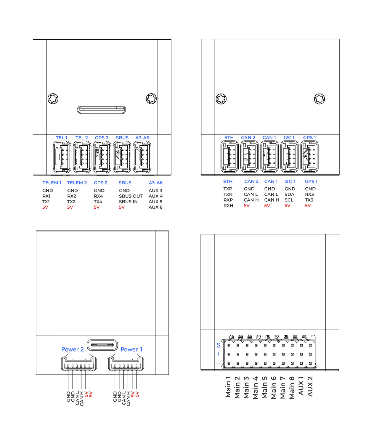
Interface Definition
UART Mapping
In the pinout diagram, UARTs are labeled as Rn and Tn. Rn is the receive pin for UARTn, and Tn is the transmit pin for UARTn.
| Name | Function | MCU pins | DMA |
|---|---|---|---|
| SERIAL0 | OTG1 | USB | - |
| SERIAL1 | Telem1 | UART7 | Enabled |
| SERIAL2 | Telem2 | UART5 | Enabled |
| SERIAL3 | GPS1 | USART1 | Enabled |
| SERIAL4 | GPS2 | UART8 | Enabled |
| SERIAL5 | Telem3 | USART2 | Enabled |
| SERIAL6 | UART4 | UART4 | Enabled |
| SERIAL7 | DEBUG | USART3 | Enabled |
| SERIAL8 | OTG-SLCAN | USB | - |
X9 CUBE Interface Definition
X9 Core Baseboard Design Resources
Users can design a baseboard based on the bottom interface of the X9 Core.
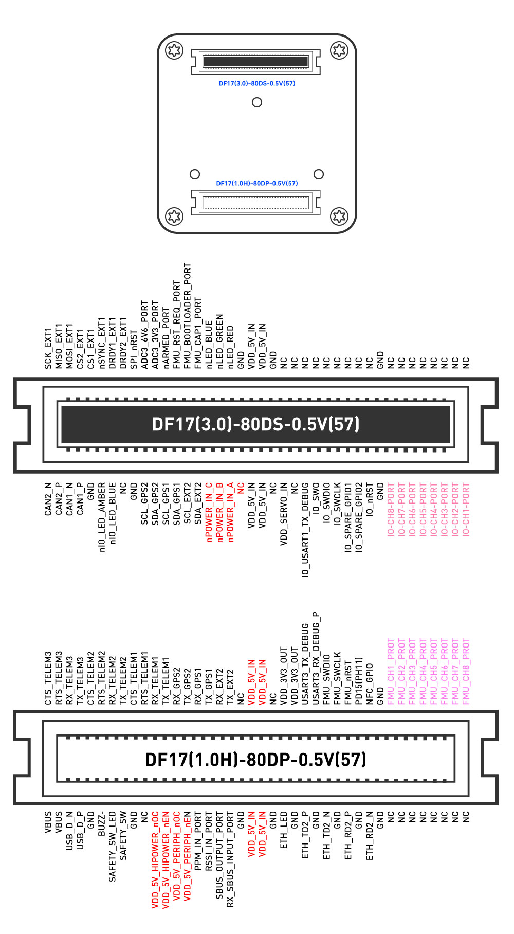
X9 Core DF17 Connector Interface Definition
The following illustration shows the bottom view of the flight controller. When designing a baseboard, users must reverse (mirror) the interface and pin definitions themselves.
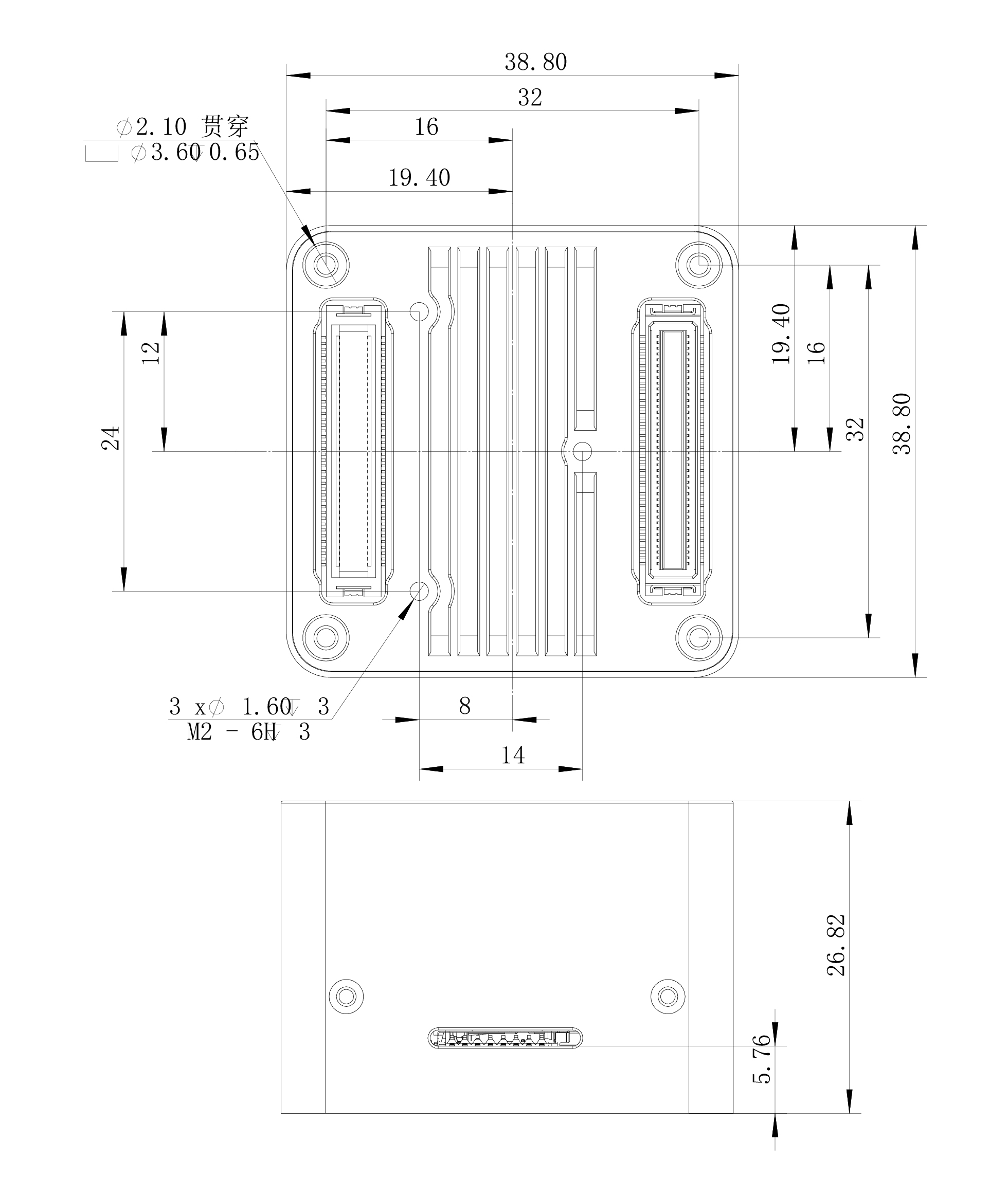
X9 Core DF17 Connector Dimension Drawing
Power Switching Module Documentation
Schematic
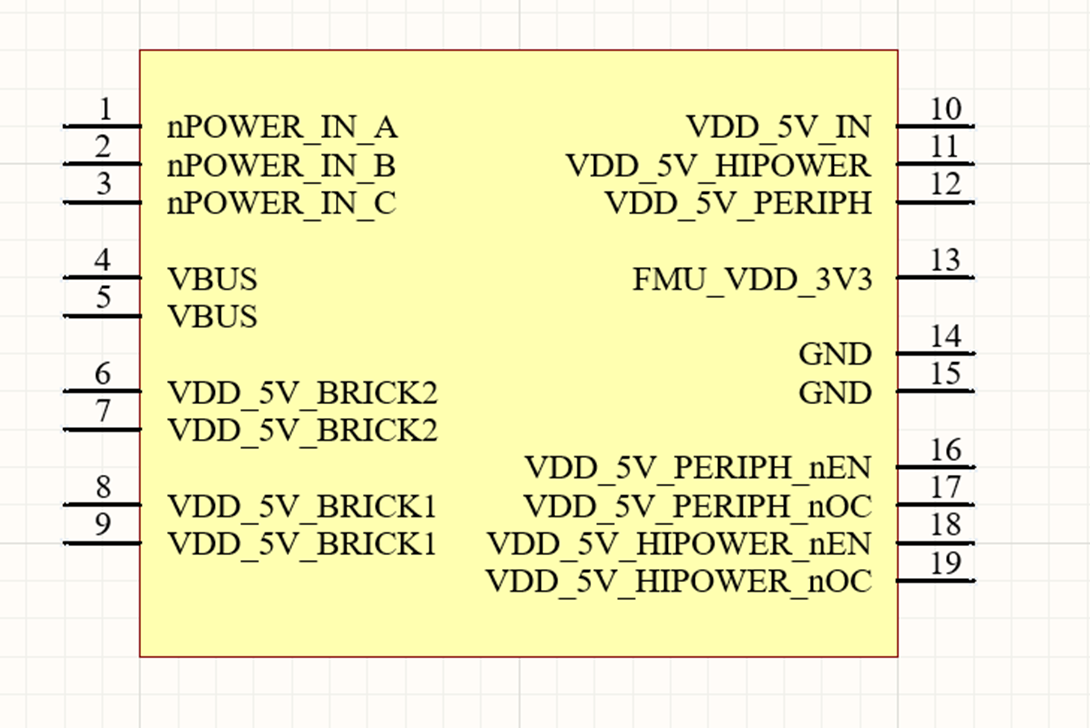
Design Reference
| Interface number | Power Switching Module Signals | Connection Target |
|---|---|---|
| 1 | nPOWER_IN_A | 【X9 CORE】nPOWER_IN_A |
| 2 | nPOWER_IN_B | 【X9 CORE】nPOWER_IN_B |
| 3 | nPOWER_IN_C | 【X9 CORE】nPOWER_IN_C |
| 4 | VBUS | 【External Input】USB |
| 5 | VBUS | 【External Input】USB |
| 6 | VDD_5V_BRICK2 | 【External Input】POWER2 |
| 7 | VDD_5V_BRICK2 | 【External Input】POWER2 |
| 8 | VDD_5V_BRICK1 | 【External Input】POWER1 |
| 9 | VDD_5V_BRICK1 | 【External Input】POWER1 |
| 10 | VDD_5V_IN | 【X9 CORE】VDD_5V_IN |
| 11 | VDD_5V_HIPOWER | 【External Input】High-Power Device Interface |
| 12 | VDD_5V_PERIPH | 【External Input】General Peripheral Interface |
| 13 | FMU_VDD_3V3 | 【Flight Controller Input】Pull-Up Voltage |
| 14 | GND | GND |
| 15 | GND | GND |
| 16 | VDD_5V_PERIPH_nEN | 【X9 CORE】VDD_5V_PERIPH_nEN |
| 17 | VDD_5V_PERIPH_nOC | 【X9 CORE】VDD_5V_PERIPH_nOC |
| 18 | VDD_5V_HIPOWER_nEN | 【X9 CORE】VDD_5V_HIPOWER_nEN |
| 19 | VDD_5V_HIPOWER_nOC | 【X9 CORE】VDD_5V_HIPOWER_nOC |
Power switching module PCB library, schematic library, and bottom board design constraints
;}.cls-2{fill:%230868f7;}.cls-3{fill:url(%23未命名的渐变_44);}.cls-4{fill:%23333;}%3c/style%3e%3clinearGradient%20id='未命名的渐变_8'%20x1='33.73'%20y1='100.61'%20x2='-0.03'%20y2='-1.06'%20gradientUnits='userSpaceOnUse'%3e%3cstop%20offset='0'%20stop-color='%237ae9fb'/%3e%3cstop%20offset='0.67'%20stop-color='%232b90f8'/%3e%3cstop%20offset='1'%20stop-color='%230868f7'/%3e%3c/linearGradient%3e%3clinearGradient%20id='未命名的渐变_44'%20x1='27.86'%20y1='18.67'%20x2='68.36'%20y2='22.22'%20gradientUnits='userSpaceOnUse'%3e%3cstop%20offset='0'%20stop-color='%235ac7f2'/%3e%3cstop%20offset='1'%20stop-color='%230868f7'/%3e%3c/linearGradient%3e%3c/defs%3e%3cpath%20class='cls-1'%20d='M29,28.74V81.91l-9.51-3.68v0L8.52,74A7.17,7.17,0,0,1,4,67.32V24.54A3.76,3.76,0,0,1,9.08,21Z'/%3e%3cpath%20class='cls-2'%20d='M68.09,78.07a13.15,13.15,0,0,1-17.9,12.06L29,81.91h0V28.74L50.19,37A13.17,13.17,0,0,0,68.08,25.3h0Z'/%3e%3cpath%20class='cls-3'%20d='M68.08,25.3a13.19,13.19,0,0,1-6.73,10.87A13.09,13.09,0,0,1,50.19,37L29,28.74V6A3.76,3.76,0,0,1,34.1,2.52l25.59,9.91A13.22,13.22,0,0,1,68.08,25.3Z'/%3e%3cpath%20class='cls-4'%20d='M129.06,81.76a4.33,4.33,0,0,1-3.19-1.31,4.4,4.4,0,0,1-1.31-3.24V56.86H97.65V77.21a4.36,4.36,0,0,1-1.35,3.2A4.68,4.68,0,0,1,93,81.76a4.32,4.32,0,0,1-3.19-1.31,4.37,4.37,0,0,1-1.32-3.24V27.27A4.58,4.58,0,0,1,89.83,24a4.59,4.59,0,0,1,7.82,3.27V48.15h26.91V27.27A4.58,4.58,0,0,1,125.91,24a4.59,4.59,0,0,1,7.82,3.27V77.21a4.37,4.37,0,0,1-1.36,3.2A4.65,4.65,0,0,1,129.06,81.76Z'/%3e%3cpath%20class='cls-4'%20d='M163.77,81.66c-6.57,0-11.76-1.92-15.44-5.7s-5.54-9.07-5.54-15.74a26.76,26.76,0,0,1,2.09-10.43,17.72,17.72,0,0,1,6.67-8.06,19.15,19.15,0,0,1,10.68-2.95,19,19,0,0,1,10.46,2.8,18.7,18.7,0,0,1,6.55,7.36,22.53,22.53,0,0,1,2.36,10.28A4.51,4.51,0,0,1,177,63.77H152.23a10.8,10.8,0,0,0,3.49,6.65c2,1.68,4.88,2.52,8.66,2.52a22.25,22.25,0,0,0,7.54-1.21c.74-.3,1.55-.67,2.37-1.07a3.75,3.75,0,0,1,1.84-.4,4.09,4.09,0,0,1,3,1.15,4,4,0,0,1,1.12,3,4.38,4.38,0,0,1-2.58,3.82,32.34,32.34,0,0,1-6.36,2.61A28.67,28.67,0,0,1,163.77,81.66ZM172.4,55.9a9.72,9.72,0,0,0-1.63-4.56A9.9,9.9,0,0,0,167,48a10.38,10.38,0,0,0-4.64-1.14,12,12,0,0,0-4.77,1.06,9.54,9.54,0,0,0-4.89,5.66,11.78,11.78,0,0,0-.51,2.3Z'/%3e%3cpath%20class='cls-4'%20d='M193,81.64a4.49,4.49,0,0,1-4.51-4.55V27.28A4.58,4.58,0,0,1,189.84,24a4.48,4.48,0,0,1,3.28-1.36A4.36,4.36,0,0,1,196.35,24a4.46,4.46,0,0,1,1.31,3.31V77.09a4.34,4.34,0,0,1-1.35,3.2A4.67,4.67,0,0,1,193,81.64Z'/%3e%3cpath%20class='cls-4'%20d='M263.79,81.71a5.7,5.7,0,0,1-4.2-1.74,5.76,5.76,0,0,1-1.73-4.19V27.37a4.58,4.58,0,0,1,1.35-3.27A4.59,4.59,0,0,1,267,27.37V72.53h24a4.58,4.58,0,0,1,3.27,7.82A4.66,4.66,0,0,1,291,81.71Z'/%3e%3cpath%20class='cls-4'%20d='M424.48,81.74a4.71,4.71,0,0,1-2.71-.88,5.43,5.43,0,0,1-1-1l-.07-.09-12.41-17-5.41,5v9.44a4.31,4.31,0,0,1-1.36,3.19,4.66,4.66,0,0,1-3.3,1.36A4.29,4.29,0,0,1,395,80.42a4.36,4.36,0,0,1-1.32-3.23V27.37A4.58,4.58,0,0,1,395,24.1a4.52,4.52,0,0,1,6.58.12,4.54,4.54,0,0,1,1.24,3.15V56.31l17.72-16.38.05,0a4.8,4.8,0,0,1,2.94-1.11,4.4,4.4,0,0,1,3.27,1.2,4.57,4.57,0,0,1,1.2,3.27,4.44,4.44,0,0,1-.77,2.33,7.45,7.45,0,0,1-1.43,1.65l-11,9.64,13.34,17.68a5,5,0,0,1,1,2.71,4.12,4.12,0,0,1-1.36,3.24A4.64,4.64,0,0,1,424.48,81.74Z'/%3e%3cpath%20class='cls-4'%20d='M317.93,81.76a21.5,21.5,0,1,1,21.17-21.5A21.37,21.37,0,0,1,317.93,81.76Zm0-34.1a12.61,12.61,0,1,0,12.42,12.6A12.52,12.52,0,0,0,317.93,47.66Z'/%3e%3cpath%20class='cls-4'%20d='M212.18,101.22a4.12,4.12,0,0,1-3.05-1.26,4.17,4.17,0,0,1-1.26-3.1V43.34a4.37,4.37,0,0,1,1.3-3.14,4.26,4.26,0,0,1,3.13-1.3,4.19,4.19,0,0,1,3.1,1.26,4.32,4.32,0,0,1,1.26,3.16,20.77,20.77,0,0,1,13-4.54,21.51,21.51,0,0,1,0,43,20.51,20.51,0,0,1-13-4.57V96.86a4.15,4.15,0,0,1-1.3,3.06A4.5,4.5,0,0,1,212.18,101.22Zm17.43-53.63c-6.23,0-12.93,4.11-12.93,12.72a12.73,12.73,0,0,0,25.46,0A12.71,12.71,0,0,0,229.61,47.59Z'/%3e%3cpath%20class='cls-4'%20d='M365.76,81.76a21.5,21.5,0,1,1,21.18-21.5A21.37,21.37,0,0,1,365.76,81.76Zm0-34.1a12.61,12.61,0,1,0,12.42,12.6A12.52,12.52,0,0,0,365.76,47.66Z'/%3e%3c/svg%3e)